Interfacing with External Devices
2 Set the following parameters.
To return the setting to the default value
Press [Default].
Setting the Monitor Output
To set the signals output from the MVE-8000A/MVE-
9000 four monitor output connectors (two connectors for
the MKS-6570), use the following procedure.
Notes
To use the monitor outputs of the MKS-6570, it is
necessary to assign them to switcher output connectors in
advance
(
1
“Assigning Output Signals” (p. 351)).
1
Open the Engineering Setup >DME >Output
>Monitor Output menu (7343.1).
2
In the <Select> group, select the DME to which the
setting applies.
3
In the list on the left of the status area, press directly on
the monitor output for which you want to make setting.
4
In the list on the right of the status area, press directly
on the signal you want to output.
5
Press [Set].
The selection is reflected in the monitor output.
Interfacing with External
Devices
Setting the Editor Protocol
This sets the protocol to be used on the editor port of the
MVE-8000A and MVE-9000.
In the <DME2 Editor Protocol> group of the Engineering
Setup >DME >Device Interface menu (7344), press the
following buttons.
DME: Control by DME protocol through the editor port.
VTR: Control by VTR protocol through the editor port.
Making Editor Port Settings
This makes settings relating to the control of the editor
ports in the MVE-8000A and MVE-9000.
In the <DME2 Editor Port Setting> group of the
Engineering Setup >DME >Device Interface menu (7344),
press either of the following to select the way in which the
editor ports are used.
Common: Control all of channels 1 to 4 through editor
ports 1 to 4.
Independ: Control channels 1 to 4 individually through
editor ports 1 to 4.
Making DME GPI Input Settings
This sets the GPI input ports and trigger type, and makes
the action settings.
The following description assumes DME1. For DME2, set
Ch5 to Ch8 in the same way.
Notes
The GPI input of the MKS-6570 is common with the GPI
input that controls the switcher processor.
1
Open the Engineering Setup >DME >Device Interface
>DME1 GPI Input menu (7344.1).
2
Select the setting.
3
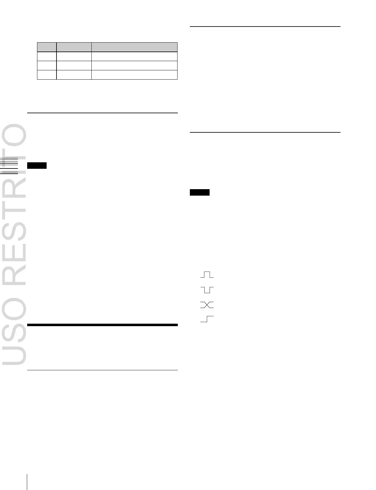
In the <Trigger Type> group, select the trigger type.
(Rising Edge): Applies the trigger on the rising
edge of an input pulse.
(Falling Edge): Applies the trigger on the
falling edge of an input pulse.
(Any Edge): Applies the trigger on a change in
the polarity of the input signal.
(Level): Carries out the specified operation
when the input is low or high.
No Operation: Applies no trigger on an input pulse.
4
In the <Target> group, select what this applies to (Ch1,
Ch2, or Proc).
5
Select the action to be set.
6
Press [Action Set] to confirm the action selection.
Selectable actions for various trigger types
•
When the trigger type is other than “Level”
When Target is Ch1 or Ch2: Freeze, SS ? Recall, Effect
? Recall, Effect ? Recall & Run, KF Run, KF Stop,
KF Rewind, KF Reverse Run, No Action
When Target is Proc: No Action
•
When the trigger type is “Level”
 Loading...


