In the 1st row, press
the button to which the
corresponding key
was assigned in the
Setup menu, turning it
on.
Chapter
3
Signal
Selection
and
Transitions
Signal Selection
You carry out signal selection in the cross-point control
block of each bank.
2nd row
1st row
These buttons are identified by numbers common to all of
the banks and blocks, and a signal is assigned to each
number.
The basis of signal selection is to select, in a cross-point
button row, the cross-point button to which the desired
signal is assigned.
Selecting M/E reentry input signals
For example, a video signal created on the M/E bank can
be imported as an input signal on the PGM/PST bank. In
this way, you can use a video created on any bank as an
input signal on another bank. These signals are referred to
as “M/E reentry input” signals.
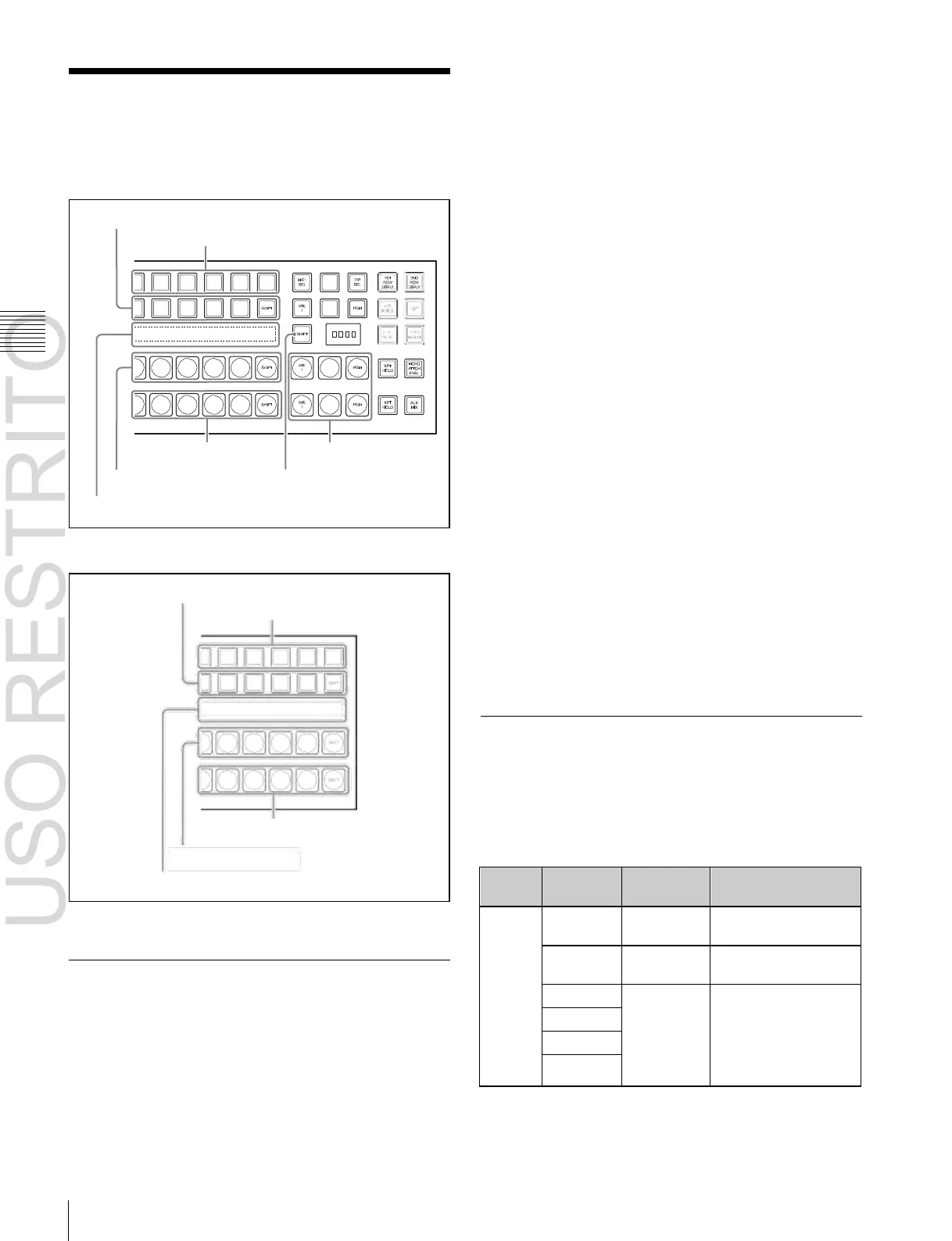
Background B row
Background A row
Source name display
Reentry buttons
Dedicated SHIFT button
To select using a reentry button (ICP-6520/6530)
Output video (M/E reentry inputs) from each bank are
assigned to the reentry buttons on the cross-point control
block.
For example, to select the reentry input from the M/E-1
bank as the background B input to the PGM/PST bank, in
the PGM/PST cross-point control block, press the [M/E1]
button in the background B row.
To select using an assignment to a cross-point
Cross-point control block (ICP-6520/6530)
2nd row
1st row
button (ICP-3000/3016)
To select an M/E reentry input signal using the cross-point
buttons, the signal must be assigned beforehand in the
Setup menu
(
1
p. 329).
For example, if the program output from the M/E-1 bank
(M/E1OUT1) is assigned to an arbitrary cross-point
button, the signal can be used as the M/E-1 reentry input at
any time.
Bus Selection
Background B row
Background A row
Source name display
Each row of cross-point buttons is shared by multiple
buses.
The following table illustrates the correspondence
between buses and cross-point button rows, and the
delegation operations.
Cross-point control block (ICP-3000/3016)
Basics of Signal Selection
Each of the switcher banks have cross-point buttons and
reentry buttons in their cross-point control blocks.
The ICP-6520 and ICP-6530 both have 24 cross-point
buttons and three reentry buttons.
The ICP-3000 and ICP-3016 have 24 and 16 cross-point
buttons, respectively. The ICP-3000 and ICP-3016 do not
have reentry buttons.

 Loading...


