About the Macro Attachment List Display 429
FrameMemory1Clip to
FrameMemory8Clip
Frame memory clip loop on/off
(a): Loop is enabled
(b): Loop is disabled
Applicable register number
Control blocks on the applicable bank
Status of function assigned to button
(a): Operates according to currently assigned
function
FrameMemory1Clip to
FrameMemory8Clip
File type of clip (pair/single)
Name of clip (up to four characters)
Aux1, Aux3, Aux5, … Aux23
Target AUX bus (odd-numbered bus)
AUX mix transition On/Off
Example of File Contents
PNL 0001PNL_0000.PMRMACROREG
Event?,Snapshot,Region?,ME1,Register?,1,Attribute?,Off,Time?,
Current
Simultaneously recall snapshots from register
number 1 in the M/E-1 and PGM/PST regions.
Continue?,Snapshot,Region?,PP,Register?,1,Attribute?,Off,Time?,
Current
Event?,MEXpt,ME?,ME1,MEBus?,A,Xpt?,1,VideoKey?,Video
Select button number 1 on the M/E-1 A bus.
About the Macro
Attachment List Display
Then, the display in the Button column is:
UTIL1 Bus V XPT2
which indicates “P/P row utility1 bus video signal, cross-
point button 2.”
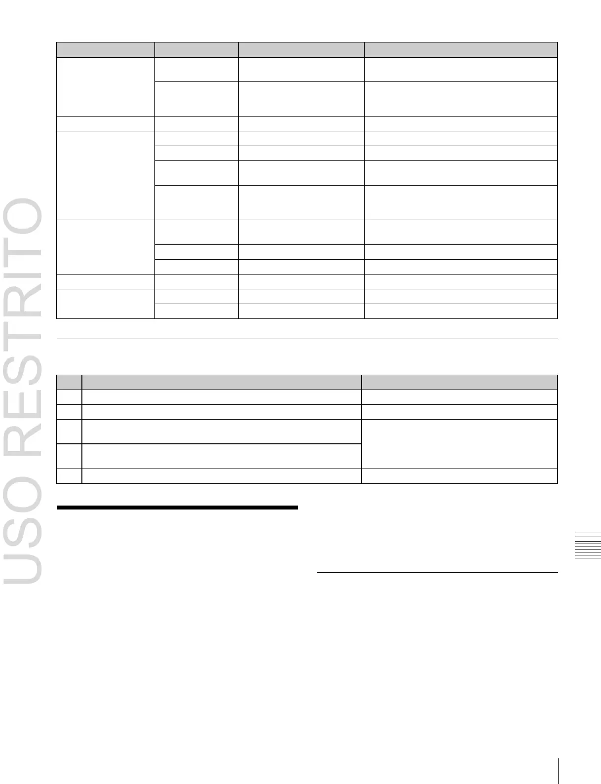
The Button column in the macro attachment list displayed
in the status area of the Macro >Attachment menu (5421)
screen shows character strings which identify macro
attachment assigned buttons.
Each of these character strings is in fact a combination of
characters shown in the Button(1), Button(2), and
Button(3) columns in the following tables.
For example, if Block and Button(1) to Button(3) are:
Block: P/P XPT
Button(1): UTIL1 Bus
Button(2): V
Button(3): XPT2
M/E and PGM/PST Banks
The following table shows only the macro attachment
assignable buttons in the PGM/PST bank.
For the M/E1 bank, “P/P” changes to “M/E1” in the Block
Select and Block columns. In addition, “DSK” changes to
“KEY” in the Button(1) and Button(2) columns. The
contents of the Button(3) column do not change.
 Loading...


