Tally Group Settings / Wiring Settings
Destination start address
Chapter
22
Router
Interface
and
Tally
Setup
Destination start address
4
In the <Device> group, select [External Box2].
5
In the <Matrix Size> group, select [32 × 1].
6
Set the parameters.
At this point, make the settings of Destination and
Level the same as in step 3.
This automatically couples External Box1 and
External Box2, forming an external box with 40
(8+32) inputs.
Setting the group number of an S-Bus
description name
Sets the group number for an S-Bus description name to be
displayed in the source name displays for a cross-point
operation.
1 In the <Alias Name Gp> group of the Engineering
Setup >Router/Tally >Router menu (7361), press [Gp
No].
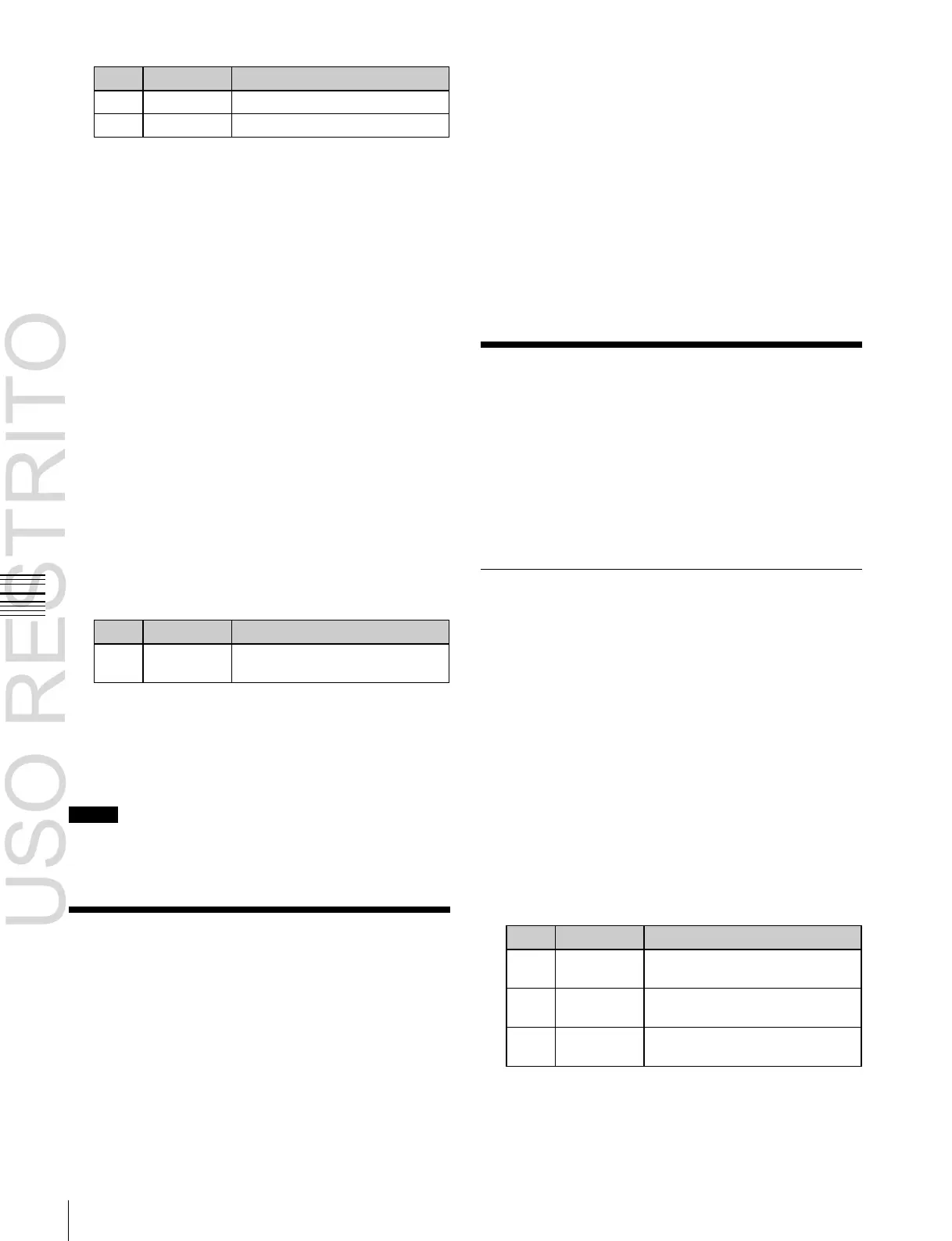
2 Set the following parameter.
Group number of S-Bus
description name
a)
a)
When setting values 1 to 7 are selected and the name is not set, the
description name for “0” appears.
If the description name for “0” is not registered either, the Type and
No values appear.
3 In the <Alias Name Gp> group, press [Set].
Notes
Transmit the description name selected here from the
router.
Tally Group Settings
With the S-Bus protocol, tally control is possible for
groups 1 to 8, but in this system you can use either groups
1 to 4 or groups 5 to 8.
You can also select whether or not to transfer the tally
information over the S-Bus.
Setting the tally groups
1
Open the Engineering Setup >Router/Tally >Group
Tally menu (7362).
2
To select a consecutive sequence of groups from each
of groups 1 to 4 and groups 5 to 8, set [All Group
Enable] to On.
3
In the <Tally Group> group, select the desired groups.
4
Set [SBus Tally Enable] to On to enable the tally
information on the S-Bus.
Wiring Settings
When configuring a system in which the switcher inputs
and outputs are connected to a router, setting this
connection configuration (referred to as “wiring”) in the S-
Bus space, or inputting the information which specifies the
physical wiring, is necessary.
The settings are common to the parallel and serial tallies.
Making New Wiring Settings
1
Open the Engineering Setup >Router/Tally >Wiring
>New menu (7363.1).
2
Set the destination.
When switcher inputs and outputs are connected to the
router in a group, you can specify the start and end
destination addresses.
Destination From: Specifies the start destination
address for the wiring configuration.
Destination To: When the wiring configuration is
multiple, specifies the end destination address. For
a single wiring connection, this setting is not
required.
Destination Level: Specifies the destination level of
the wiring configuration.
 Loading...


