8
Set the disk recorder response speed.
9
Press [Delay Set].
10
Repeat steps 4 to 9 as required to make the settings for
other commands.
Making detailed settings for a VTR
1
In the Engineering Setup >DCU >Serial Port Assign
menu (7355), select the setting target (DCU1 or
DCU2) from the <DCU Select> group.
2
Select the serial port connected to the VTR for which
you want to make the settings.
Notes
When the MKS-2700 is connected, select 2 for the slot
and a value in the range 1 to 6 for the port.
3
Press [Port Setting].
The VTR Setting menu (7355.2) appears.
At the top of the status area, the relevant serial port,
slot number, device type, serial port name, SCU
number, and timecode source appear. In the lower part
of the status area, the VTR constants appear.
4
In the <TC Source> group, select the timecode source
(reference signal for determining the tape position)
from the following.
LTC (Longitudinal Time Code): Uses LTC. When
interpolation data is returned from a VTR, use that
interpolation data.
LTC:VITC (Vertical Interval Time Code):
Normally uses LTC, but when the tape is moving
at speeds at which LTC cannot be read, use VITC.
When interpolation data is returned from a VTR,
use that interpolation data.
VITC: Uses VITC.
CTL (Control): Uses CTL pulses or timer counter
pulses. Use this only for a tape on which no
timecode is recorded.
The displayed tape position is based on the reference
signal specified here.
5
Specify the VTR constants to set.
6
Press [Set].
A numeric keypad window for hexadecimal input
appears.
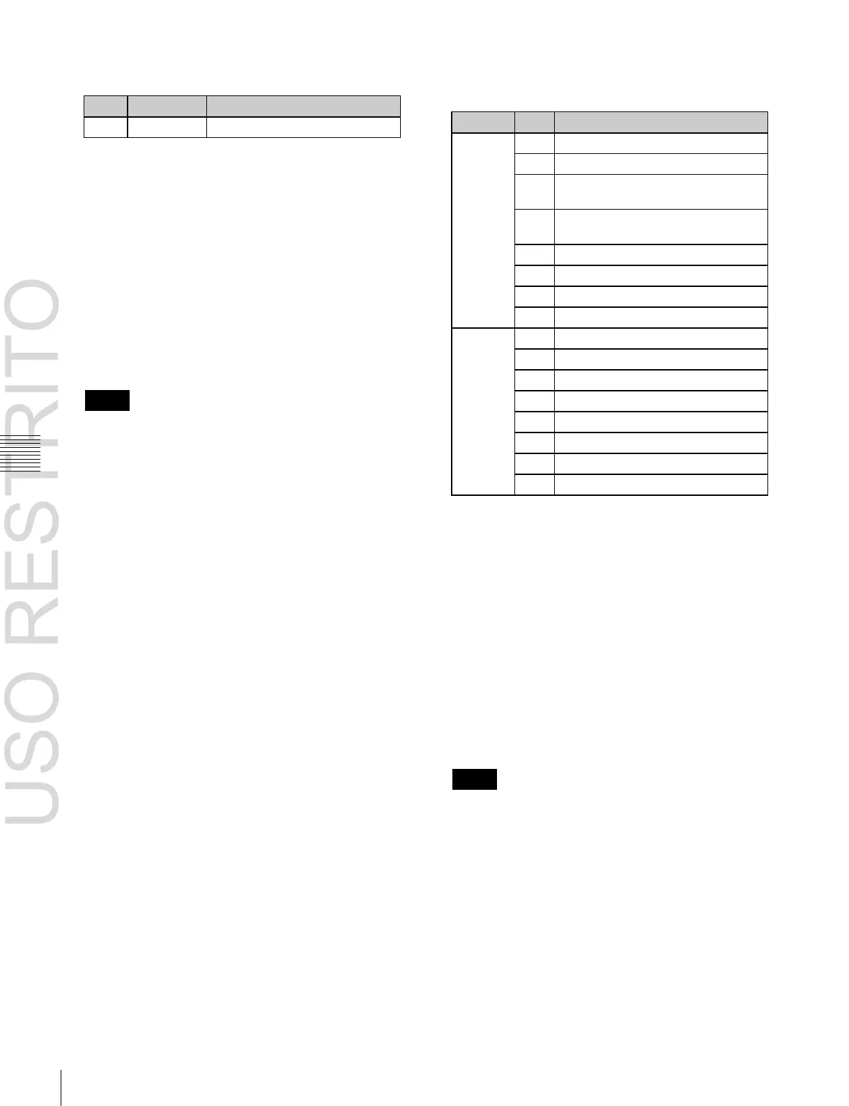
7
Set the VTR constants using values in the range 00 to
FF.
HI-BYTE (FRAME) (PREROLL
TIME)
LO-BYTE (FRAME) (PREROLL
TIME)
QUICK PVW PRRL TIME (FRAME)
8
Press [Enter].
9
Repeat steps 5 to 8 as required to set the constants for
other VTRs.
Making detailed settings for a disk
recorder (Sony disk 9-pin protocol)
1
In the Engineering Setup >DCU >Serial Port Assign
menu (7355), select the setting target (DCU1 or
DCU2) from the <DCU Select> group.
2
Select the serial port connected to the disk recorder for
which you want to make the settings.
Notes
When the MKS-2700 is connected, select 2 for the slot
and a value in the range 1 to 6 for the port.
3
Press [Port Setting].
The DDR SD9P Setting menu (7355.3) appears.
At the top of the status area, the relevant serial port,
slot number, device type, serial port name, SCU
number, and disk recorder type appear. In the lower
part of the status area, the response speed settings
appear.

 Loading...


