7-26
764333-675
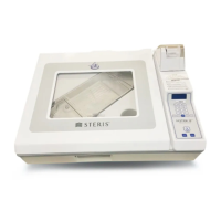
17. For horizontal mounted chambers, install fan
bracket. Once fan bracket is installed or for
vertically mounted chambers install sleeve bolt
and turn it 90° clockwise, expect resistance when
seating the o-ring. Lock with 10-24 x ¾" pan head
screw as shown in Figure 7-38.
18. For horizontally mounted chambers, install fan on
fan bracket using the four pan head screws to
secure fan in place.
19. Quartz sleeve is now installed and sealed.
20. See S
ECTION 7.24, UV LAMP REPLACEMENT Steps 7
through 10 for lamp installation. Reinstall lamp,
lamp socket and shroud cover.
7.26 UV POWER SUPPLY FUSE
REPLACEMENT
The UV water treatment system is equipped with one
functioning and one spare 250V, 2 Amp fuse. To
replace fuse follow the steps below.
1. Unplug the power cord from the wall receptacle
then disconnect power cord from the right side of
the power supply.
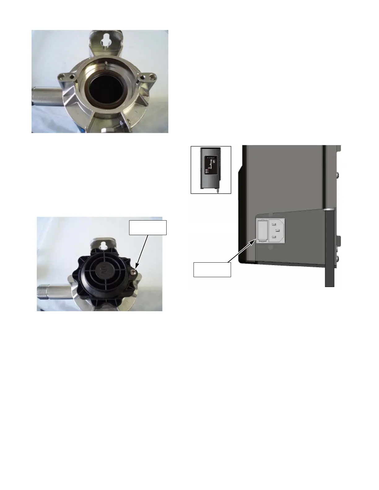
2. Remove fuse door by pushing in the tap on one side
using a small flat blade screw driver and gently
prying outwards. Repeat on the other side of door
and pull fuse holder out of unit. See Figure 7-39 for
fuse door location.
3. Replace blown fuse with spare and replace spare
with a new 250V, 2 Amp fuse.
4. Reinstall fuse holder into power supply noting the
location of the functioning fuse versus spare fuse.
5. Plug power cord back into power supply.
6. Plug power cord back into wall receptacle.
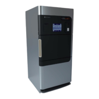
Figure 7-37. Install Opposite-End Quartz
Sleeve O-Ring
Figure 7-38. Lock Shroud with Pan-Head Screw
Figure 7-39. Fuse Door Location
 Loading...