7-8
764333-675
9. Exercise pinch sleeves.
a. Enter service mode (see S
ECTION 2) and
manually activate and deactivate the pinch
sleeve.
b. Enter valve test. Turn on S1 to inflate the drain
pinch sleeve.
c. Turn on S4 to activate the drain pinch sleeve.
d. Turn on S3 to activate the circulation pinch
sleeve.
e. Leave activated for 5 - 10 seconds.
f. Turn off S4 and S3.
g. Leave activated for 10 - 15 seconds.
h. Repeat steps c through g as necessary.
The exercising routine is a temporary measure
designed to optimize pinch sleeve performance.
Pinch sleeve materials may be changed in the future
to improve durability and performance.
10.Re-install shroud, and run a test cycle. If no leaks
are observed, place unit back into service.
7.9 CONCENTRATION PROBE
CLEANING
Equipment, Fixtures, Special Tools:
1. Vinegar
2. Scotch Brite™
1
Pad
Procedure:
Scale on concentration probes may be corrected in one
of three ways:
1. Pour vinegar into port and allow to sit for 15
minutes.
2. Probe depth is factory set and is critical to proper
operation. Mark probe depth before removing to
clean. Remove probes and clean with Scotch Brite
pad. Reinstall probe at marked position.
3. If scale is too heavy, replace probe and block.
7.10 SEAL PRESSURE
REGULATOR/COMPRESSOR
OUTPUT TEST
Procedure:
1. Connect pressure gauge to bulkhead fitting at back
of SYSTEM 1E Liquid Chemical Sterilant Processing
System.
2. Energize compressor.
3. Measure output pressure of compressor. Maximum
acceptable pressure is 44 psi (303.4 kPa).
WARNING – PERSONAL INJURY
HAZARD: Disconnect all utilities to
SYSTEM 1E Liquid Chemical Sterilant
Processing System before servicing. Do not
service the SYSTEM 1E Liquid Chemical Sterilant
Processing System unless all utilities have been
properly locked out. Always follow OSHA Lockout-
Tagout and electrical safety-related work practice
standards.
WARNING – PERSONAL INJURY and/or
EQUIPMENT DAMAGE HAZARD: Repairs
and adjustments to this equipment must
be made only by fully qualified service personnel.
Maintenance performed by inexperienced,
unqualified personnel or installation of
unauthorized parts could cause personal injury,
invalidate the warranty, or result in costly
equipment damage. Contact STERIS regarding
service options.
7.11 POWER SUPPLY
Procedure:
1. Turn OFF power and shut off water supply. Follow
lock-out/tag-out procedures.
2. Remove lower shroud.
3. Remove control box cover.
4. Remove four mounting screws.
5. Slide power supply upward, and remove two
connectors.
NOTE: The larger connector requires use of a small
flat-blade screwdriver to disengage the snap lock
in order to remove it.
6. Remove insulating pad from old power supply and
attach to new power supply.
7. Install new power supply by following the steps
outlined above in reverse order.
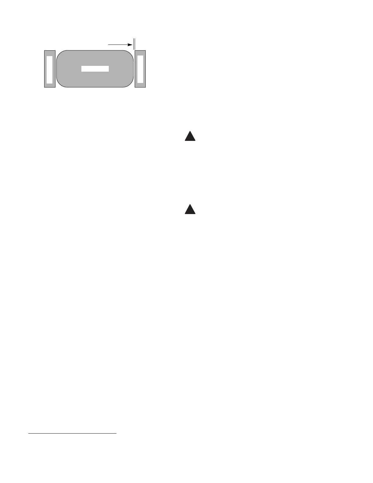
Figure 7-14. Pinch Valve Gap Adjustment
1. Scotch Brite™ is a trademark of 3M.
Valve Body
0.030" (0.76 mm) Gap
Valve Cap
Valve Cap
 Loading...