6-1
764333-675
6.1 GENERAL
This section is to be used to verify that the
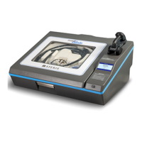
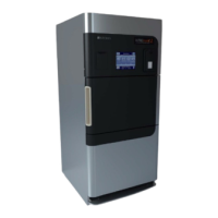
SYSTEM 1E™ Liquid Chemical Sterilant Processing
System is operating within manufacturer’s
specification. Field test procedures are used in addition
to the DIAGNOSTIC Cycle for the SYSTEM 1E Liquid
Chemical Sterilant Processing System to evaluate
various components. Field test procedures are to be
performed by qualified trained service personnel with
appropriate test instrumentation.
6.2 TEST INSTRUMENTATION
The following instrumentation is utilized in this
section:
1. Calibrated potentiometer and thermocouple leads.
2. Calibrated pressure gauge.
3. Digital VOM.
6.3 INSTALLATION VERIFICATION
Refer to the Site Prep Guide for the SYSTEM 1E
Processor. It is necessary to verify the following
utilities:
1. Water pressure: Minimum 40 psi; preferred, 50 to
60 psi.
2. Water temperature: 43 to 60°C (110 to 140°F);
46 to 48°C (115 to 118°F) recommended for
optimum cycle times.
3. Water flow rate: Minimum, 2.5 gpm.
4. Electrical Voltage: 115Vac (+5% / -10%).
5. GFI circuit: Trips when test button depressed.
6. Drain piping diameter: 1-¼” I.D. diameter
minimum.
7. Drain piping slope: Hoses must slope downward
and not have any dips/bows.
8. Water supply piping: ½” diameter minimum.
9. Level of mounting surface: Level with use of a spirit
level or equivalent.
10. Room temperature: 60 to 90°F (16 to 32°C).
6.4 TEST PROCEDURES
6.4.1 Pressure Transducer Calibration
For calibration procedures, refer to SECTION 2,
SERVICE MODE.
6.4.2 Temperature Calibration
For Temperature Calibration procedure, refer to
SECTION 2, SERVICE MODE.
6.4.3 Concentration Monitor Calibration
For concentration monitor calibration procedure,
refer to SECTION 2, SERVICE MODE.
6.4.4 UV Monitor Calibration
For UV monitor calibration procedure, refer to
SECTION 2, SERVICE MODE.
6.4.5 HP Pump Flow Rate And Pressure Test
The check for HP pump flow rate and pressure utilizes
the same measurement equipment. The tray is
removed for this test. The manipulation of the
SYSTEM 1E Liquid Chemical Sterilant Processing
System valves and pump differs and are discussed
separately.
Equipment – Use kit (P/N 764329-097), consisting of
plumbing fittings needed to adapt to STERIS Heise
pressure gauge. A flask or similar container capable of
measuring 2 L (0.53 gal) is also required. Substitution
of an accurate pressure gauge is acceptable. The tubing
supplied in the kit is attached to the high-pressure
quick disconnect post with a hose clamp. For the flow
test, the hose is directed to the 2 L (0.53 gal) container.
For the pressure test, the hose is connected to the gauge.
For the flow rate test an acceptable range is 2 L
(0.53 gal) in 37 to 57 seconds (3.2 to 2.1 lpm). For the
pressure test, an acceptable range is 13.5 to 19.5 psi for
60Hz.
• Procedure
1. Leaving lid open, enter service mode. Select TESTS,
and then select VALVES.
2. Inflate seal by turning ON s1 (SOL1).
3. Close drain pinch valve by turning ON s4 (SOL4).
4. Fill drain pan with water by turning ON s7 (SOL7).
Allow water to fill drip pan until water is about 1-¾”
Section 6: Field Test Procedure
 Loading...
