7-5
764333-675
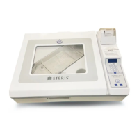
11. Loosen the 8-32 setscrew from gas spring cylinder
locking clevis pin.
WARNING – PERSONAL INJURY OR
EQUIPMENT DAMAGE HAZARD: Lid
assembly is heavy. Always support lid
assembly when gas spring cylinder is removed.
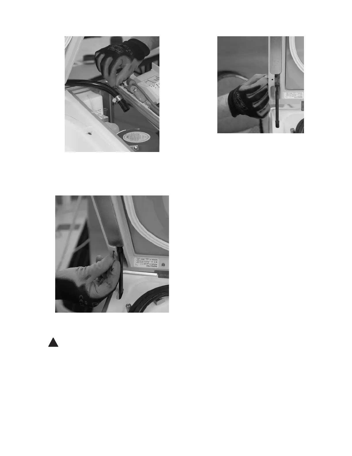
12. Thread an 8-32 screw into threaded hole of locking
clevis pin. Hold lid open with right hand and pull
clevis pin out using 8-32 screw with left hand. Lean
lid assembly back past 90° position and support in
place.
13. Support the control assembly with right hand and
remove two remaining screws from control hinges.
Lift drip pan assembly from front edge so trim
band is removed from lower shroud and slide
control assembly through drip pan band opening
and set on electronics enclosure.
14. Secure control assembly back to the frame using
one screw into each hinge.
15. Secure lid assembly by reinstalling clevis pin into
gas spring cylinder.
16. Replaceable components are now accessible and
available for servicing.
7.4 ASPIRATOR ASSEMBLY LEAK
TEST PROCEDURE
Equipment, Fixtures, Special Tools:
1. Container with approximately 6" (152 mm) of water.
2.Length of 1/8" tubing (approximately 12"
[305 mm]).
3. 50 cc syringe.
Procedure:
1. Remove aspirator to be tested from tubing on
adapter tray.
2. Install 1/8" tubing onto aspirator’s 90° elbow and
attach other end of tubing to syringe.
3. Plug orifice on end of aspirator probe with finger.
4. Submerge top of aspirator in water.
5. Using syringe, force air into aspirator and check for
leaks, air bubbles. If leaks occur, aspirator should
be replaced.
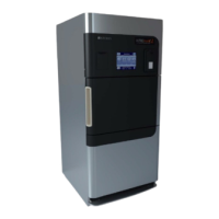
Figure 7-9. Loosen Control Hinge Screws
Figure 7-10. Loosen Gas Spring Setscrew
Figure 7-11. Remove Gas Spring Clevis Pin
 Loading...