7-21
764333-675
Quartz Hi-Hat Assembly:
Special Tools:
Sensor Tool – STERIS part number, 10006361.
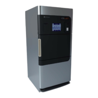
1. Use sensor tool to unthread white sensor nipple
from UV chamber (see Figure 7-27).
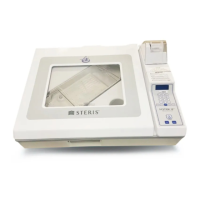
2. Reverse tool and remove the sensor sleeve (see
Figure 7-28).
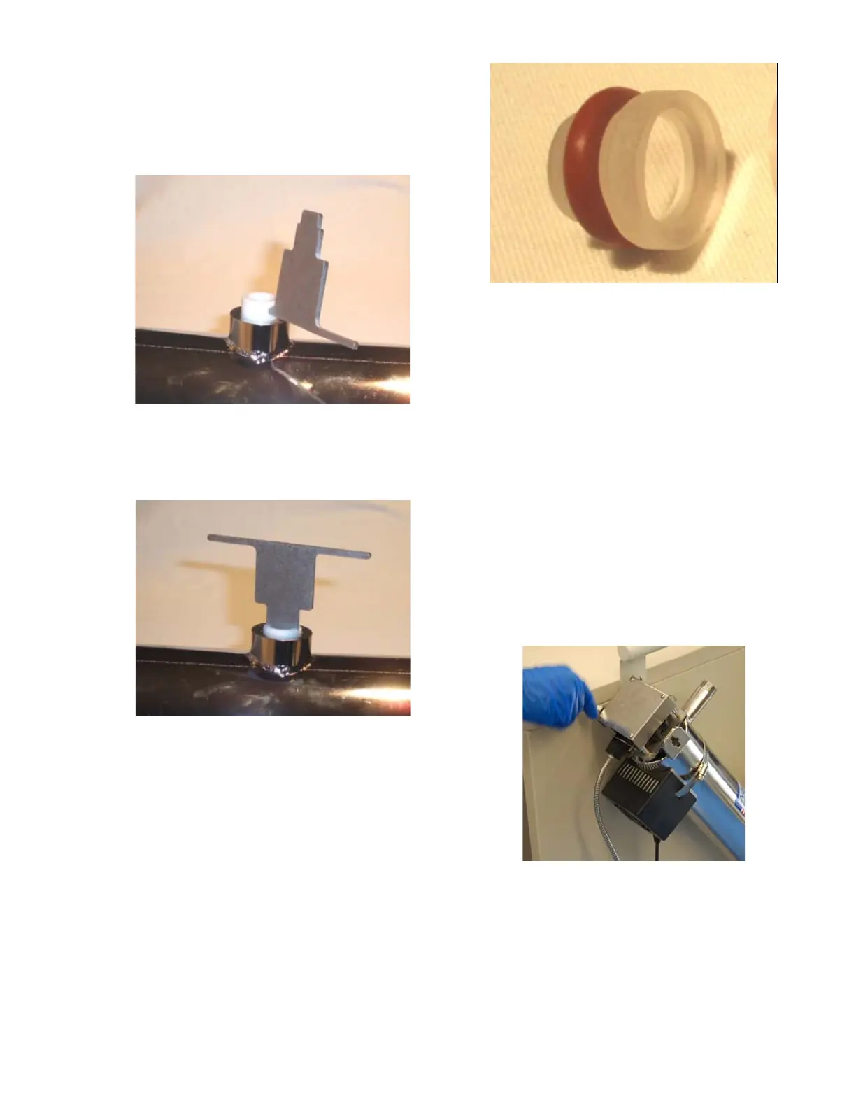
3. Remove Quartz Hi-Hat and O-ring from chamber
by tilting chamber to one side and allowing the
quartz Hi-Hat to drop out (see Figure 7-29).
4. Reinstall components in reverse order. Avoid over
tightening the sensor sleeve. The sleeve should be
tightened enough to compress the O-ring on the
Quartz Hi-Hat. Thread the sensor nipple with the
tool hole exposed (see Figure 7-20).
5. Install new UV sensor with O-rings installed. Hand
tighten brass nut. Do not use a wrench to tighten
brass nut.
7.24 UV LAMP REPLACEMENT
1. Unplug UV System from facility GFCI receptacle.
2. Turn off incoming water supply valve to UV System
and allow unit to cool for 10 minutes.
3. Remove four pan-head screws from the shroud
cover as shown below (see Figure 7-23).
Figure 7-20. Unthread Sensor Nipple
Figure 7-21. Remove Sensor Sleeve
Figure 7-22. O-Ring and Quartz Hi-Hat
Figure 7-23. Remove Screws from Shroud
Cover
 Loading...