7-3
764333-675
14. Insert 0.020” thick shim between latch pawl and
latch hook. Voltage reading should be zero.
15. Without removing 0.020” thick shim, insert an
additional 0.060” (total 0.080”) thick shim. Voltage
reading should read 5 V.
NOTE: If specifications in Steps 14 and 15 are
not met, the latch flag must be re-adjusted.
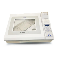
16. See Figure 7-3. Bend leg (1) until flag edge (2)
touches 0.020” shim installed and leg (1) touches
pin.
17. See Figure 7-3. Insert 0.060” shim (Total 0.080”)
between latch pawl, latch hook, and flag edge (2).
Voltage should read 5 V. If not, bend leg (3) away
from sensor, flag edge (2) is touching shims, and
leg (1) is touching pin.
18. Remove shims from assembly.
19. Remove VOM from CN9 connector.
20. Reinstall shroud.
21. Remove caps previously installed, and re-connect
inlet water hose to plastic valve fitting and drain
hose to brass male fitting on opposite side.
22. Reinstall lid on electronics control box.
23. Plug unit into wall receptacle and run test cycles.
7.3 DRIP PAN ASSEMBLY
REPLACEMENT
NOTE: Replaceable components should be serviced
by removing the drip pan assembly without turning the
unit over. The lower shroud only needs to be removed
when servicing the lower gas spring cylinder mount,
the lid latch assembly, removal of air manifold
assembly and circulation pump. Follow the lower
shroud removal procedure for safe lifting and removal
when required.
Important: This procedure should only be performed
by STERIS-trained technicians.
1. Unplug the processor from GFCI receptacle.
2. Open lid assembly and remove tray.
3. Remove any residue water in drip pan assembly.
Using a syringe with a piece of tubing suction water
from the large and small drogues until empty.
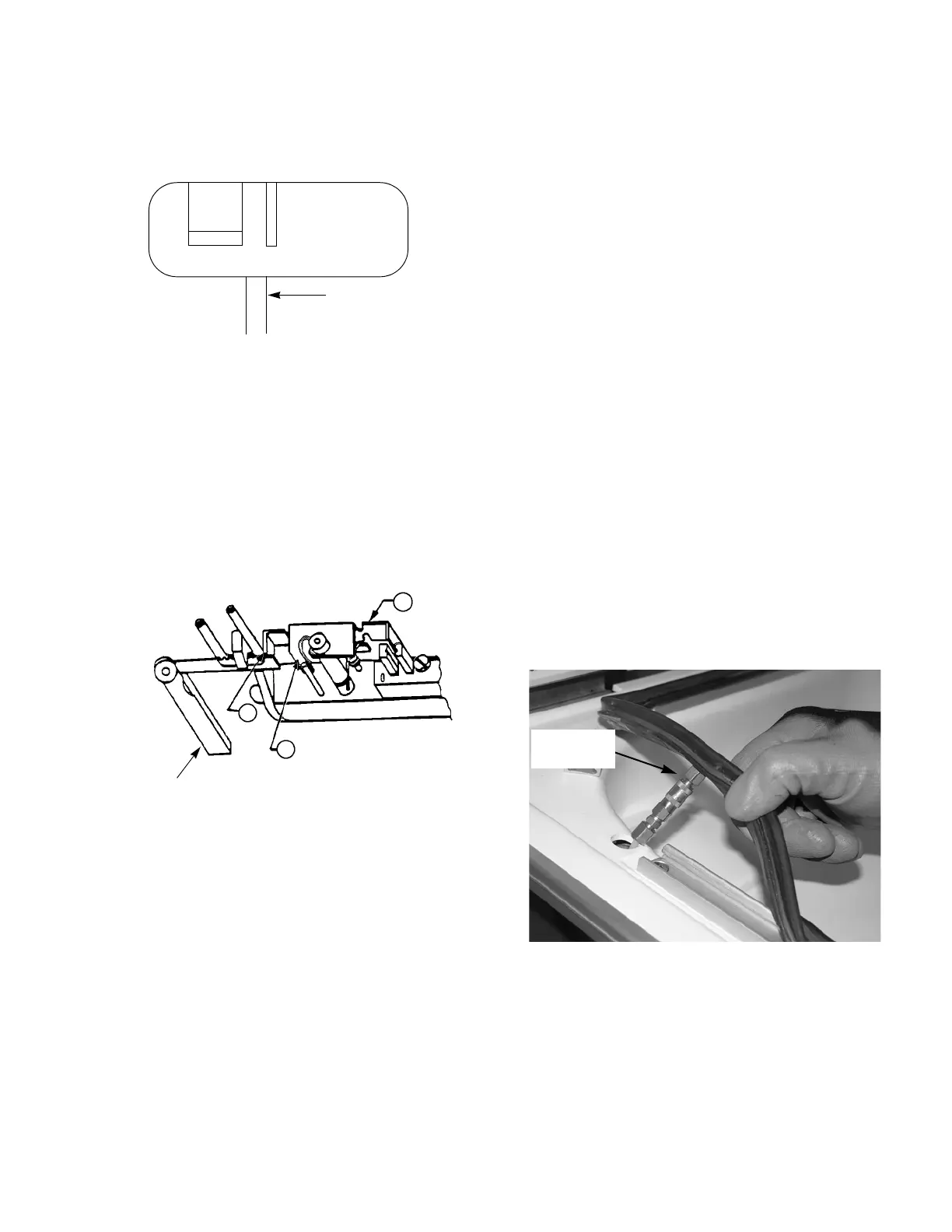
4. On the left side on the inflatable seal lift up to gain
access to the quick connect air line. Disconnect air
line.
5. Remove inflatable seal from retaining bars and clips
and set aside.
6. Remove two screws from each of the four retaining
bars.
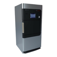
Figure 7-2. Lid Latch Hook Adjustment
Figure 7-3. Lid Latch Flag Adjustment
Latch Flag
Latching
Hook
Should be approximately
parallel
Figure 7-4. Disconnect Quick Disconnect
Seal Coupler
 Loading...