4-34 FI SYSTEM DIAGNOSIS
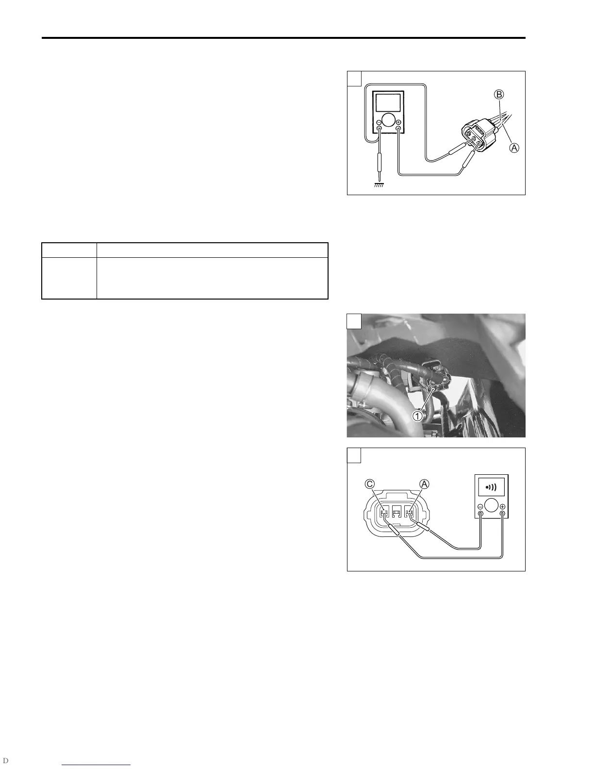
4) Disconnect the IAP sensor coupler.
5) Turn the ignition switch ON.
6) Measure the voltage at the O/Bl wire and ground.
7) If OK, then measure the voltage at the O/Bl wire
A and B
wire
B.
$ IAP sensor input voltage: 4.5 – 5.5 V
(
+ O/Bl –
- Ground)
(
+ O/Bl –
- B)
! 09900-25008: Multi-circuit tester set
& Tester knob indication: Voltage (')
Is the voltage OK?
Step 1 (When indicating P0105-H:)
1) Turn the ignition switch OFF.
2) Remove the front frame cover. (#8-8)
3) Check the IAP sensor coupler
1 for loose or poor contacts.
If OK, then check the IAP sensor lead wire continuity.
4) Disconnect the IAP sensor coupler.
5) Check the continuity between O/Bl wire
A and P wire
C.
If the sound is not heard from the tester, the circuit condition
is OK.
YES Go to Step 2.
NO
• Loose or poor contacts on the ECM coupler
(terminal
9 or
J).
• Open or short circuit in the O/Bl wire or B wire.
V
1
1
1
]

 Loading...


