8-20 CHASSIS
REMOVAL
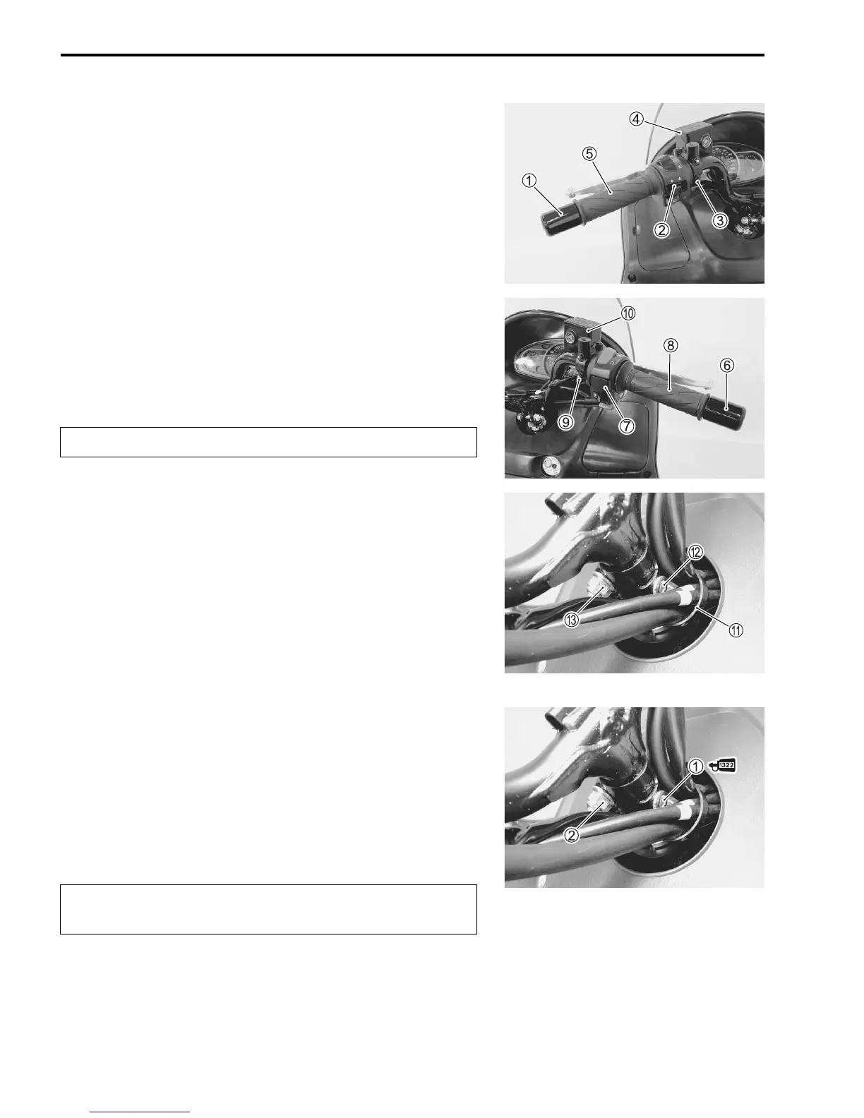
• Remove the handlebar covers. ("8-4)
• Remove the following items from the handlebars.
1 Handlebar balancer
2 Left handlebar switch box
3 Rear brake light switch lead wires
4 Rear brake master cylinder
5 Grip rubber
6 Handlebar balancer
7 Right handlebar switch box
8 Throttle grip
9 Front brake light switch lead wires
0 Front brake master cylinder
#
• Remove the clamp
A.
• Remove the handlebar set bolt
B and clamp bolt
C.
• Remove the handlebars.
INSTALLATION
Installation is in the reverse order of removal. Pay attention to
the following points:
• Tighten the handlebar set bolt
1 and clamp nut
2 to the
specified torque.
$ Handlebar set bolt: 25 N·m (2.5 kgf-m)
Handlebar clamp nut: 50 N·m (5.0 kgf-m)
#
* 99000-32110: THREAD LOCK SUPER “1322”
or equivalent
Do not turn the brake master cylinders upside down.
Apply THREAD LOCK SUPER to the handlebar set
bolt.
 Loading...


