9-20 ELECTRICAL SYSTEM
SIDE-STAND/IGNITION INTERLOCK
SYSTEM PARTS INSPECTION
Check the interlock system for proper operation. If the interlock
system does not operate properly, check each component for
damage or abnormalities. If any abnormality is found, replace
the component with a new one.
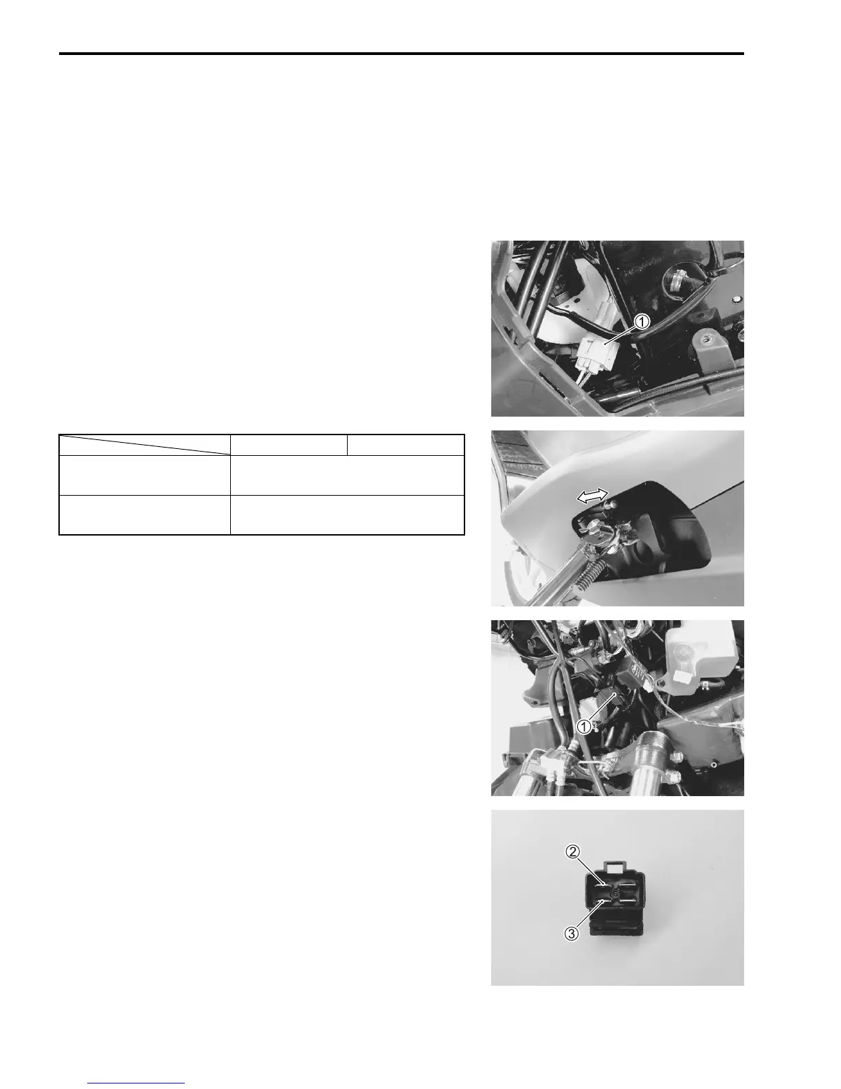
SIDE-STAND SWITCH INSPECTION
• Remove the front frame cover. (!8-8)
• Disconnect the side-stand switch coupler
1.
• Measure the voltage between G and B/W lead wire.
If the resistance is out of specification, replace the switch.
" 09900-25008: Multi-circuit tester set
) Tester knob indication: Diode test (*)
NOTE:
If the tester reads under 1.4 V when the tester probes are not
connected, replace its battery.
SIDE-STAND RELAY INSPECTION
• Remove the front leg shield. (!8-6)
• Remove the side-stand relay
1.
Check that no continuity exists between the terminals
2 and
3.
If continuity is found, replace the relay.
" 09900-25008: Multi-circuit tester
, Tester knob indication: Continuity test (-)
G (
+ probe) B/W (
- probe)
ON
(Side-stand up)
0.4 – 0.6 V
OFF
(Side-stand down)
1.4 V and more
(Tester’s battery voltage)
 Loading...


