FI SYSTEM DIAGNOSIS 4-33
“13” (P0105-H/L) IAP SENSOR CIRCUIT MALFUNCTION
INSPECTION
Step 1 (When indicating 13:)
1) Turn the ignition switch OFF.
2) Remove the front frame cover. (#8-8)
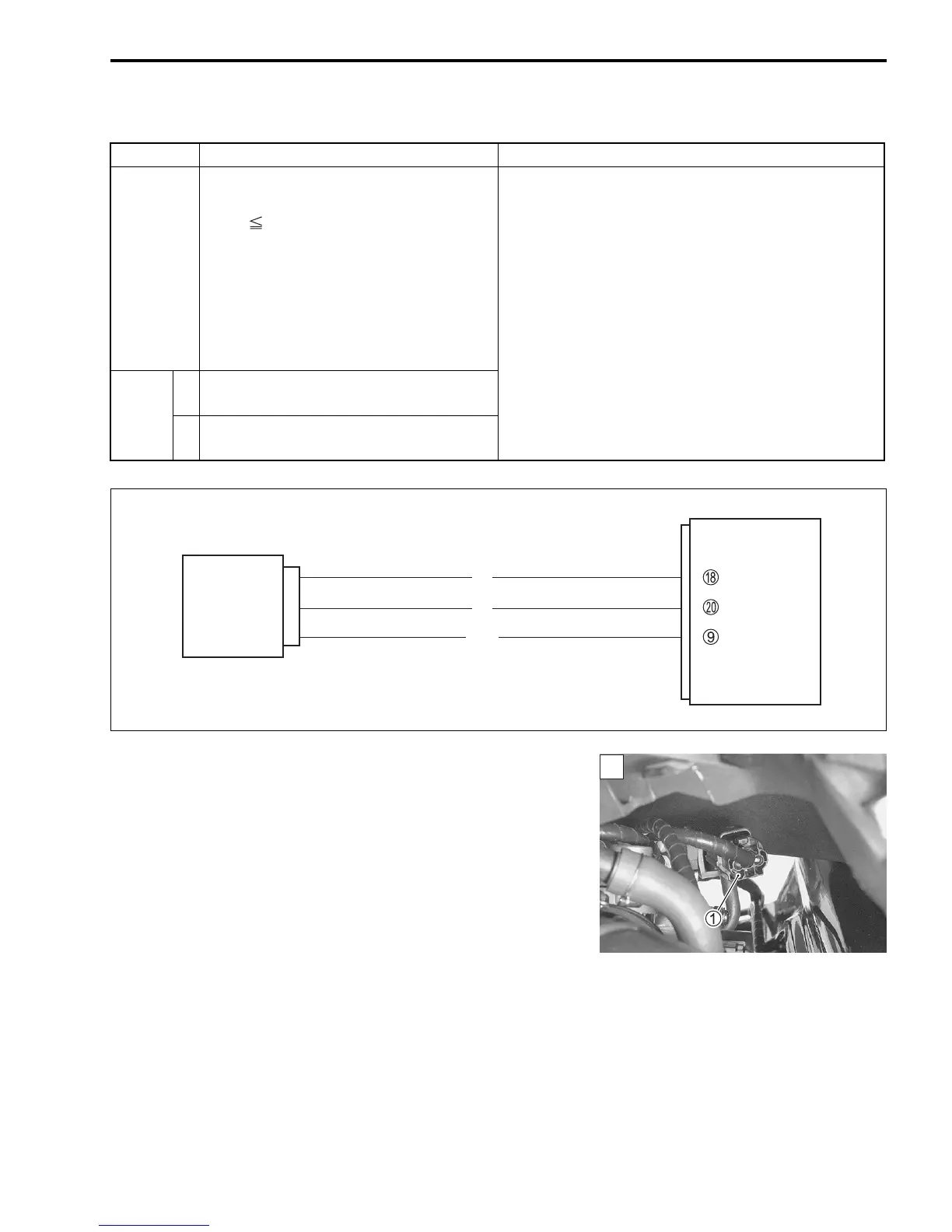
3) Check the IAP sensor coupler
1 for loose or poor contacts.
If OK, then measure the IAP sensor input voltage.
DETECTED CONDITION POSSIBLE CAUSE
13 IAP sensor voltage is not within the fol-
lowing range.
0.5 V Sensor voltage < 4.85 V
NOTE:
Note that atmospheric pressure varies
depending on weather conditions as
well as altitude.
Take that into consideration when
inspecting voltage.
• Clogged vacuum passage between throttle body
and IAP sensor.
• Air being drawn from vacuum passage between
throttle body and IAP sensor.
• IAP sensor circuit open or shorted to ground.
• IAP sensor malfunction.
• ECM malfunction.
P0105
H
Sensor voltage is higher than specified
value.
• IAP sensor circuit open or shorted to VCC or
ground circuit open.
• IAP sensor circuit shorted to ground or VCC cir-
cuit open.
L
Sensor voltage is lower than specified
value.
ECM
VCC
IAP
E2
IAP sensor
O/Bl
B
P
1
 Loading...


