ELECTRICAL SYSTEM 9-21
Check there is continuity between the terminals
2 and
3 when
12 V battery voltage is applied; positive to the terminal
4 and
negative to the terminal
5. If no continuity is noted, the relay
must be replaced.
TURN SIGNAL RELAY INSPECTION
• Remove the front leg shield. (!8-6)
If the turn signal light does not light, inspect the bulb, turn signal
switch and circuit connection.
If the bulb, turn signal switch and circuit connection checked are
all right, the turn signal relay may be faulty, replace it with a new
one.
NOTE:
Be sure that the battery is in fully-charged condition.
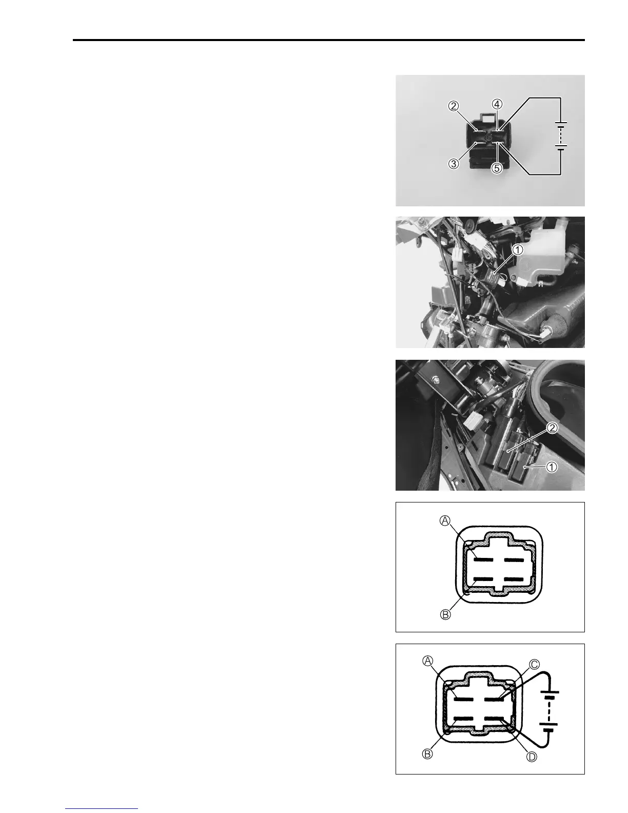
MAIN RELAY AND BRAKE START RELAY
Main relay and brake start relay can be checked in the same
way.
• Remove the main relay
1 or brake start relay
2.
• Check that no continuity exists between the terminals
A and
B. If continuity is found, replace the relay.
" 09900-25008: Multi-circuit tester set
, Tester knob indication: Continuity test (-)
• Check there is continuity between the terminals
A and
B
when 12V battery voltage is applied; positive to the terminal
C and negative to the terminal
D. If no continuity is noted,
the relay must be replaced.

 Loading...


