4-46 FI SYSTEM DIAGNOSIS
Step 2
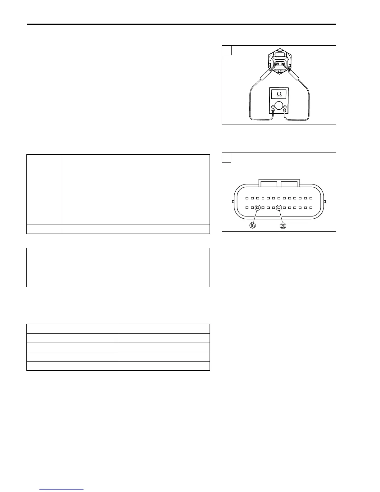
1) Turn the ignition switch OFF.
2) Disconnect the ECT sensor coupler.
3) Measure the ECT sensor resistance.
$ ECT sensor resistance: Approx. 2.45 kΩ at 20 °C
(Terminal – Terminal)
! 09900-25008: Multi-circuit tester set
% Tester knob indication: Resistance (Ω)
Refer to page 7-10 for details.
Is the resistance OK?
"
4) After repairing the trouble, clear the DTC using SDS tool.
(#4-26)
$ ECT sensor specification
YES
• W/Bl or B wire open or shorted to ground, or
poor
F or
J connection.
• If wire and connection are OK, intermittent trou-
ble or faulty ECM.
• Recheck each terminal and wire harness for
open circuit and poor connection.
• Replace the ECM with a known good one, and
inspect it again.
NO Replace the ECT sensor with a new one.
When using the multi-circuit tester, do not strongly
touch the terminal of the ECM coupler with a needle
pointed tester probe to prevent the terminal damage
or terminal bend.
Engine Coolant Temp Resistance
20 °C Approx. 2.45 kΩ
50 °C Approx. 0.811 kΩ
80 °C Approx. 0.318 kΩ
110 °C Approx. 0.142 kΩ
2
2
ECM coupler (Harness side)

 Loading...


