FI SYSTEM DIAGNOSIS 4-61
7) Disconnect the ECM coupler.
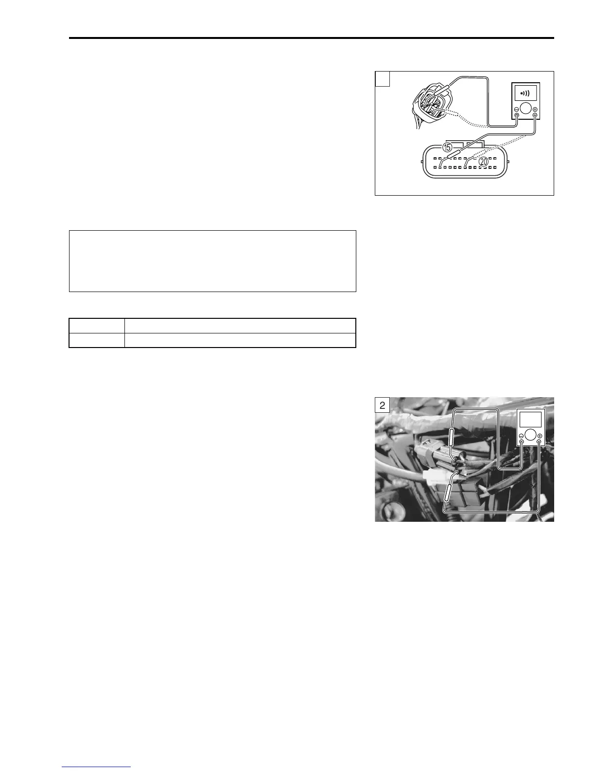
8) Check the continuity between Bl wire (harness side) and ter-
minal
E.
9) Also, check the continuity between B wire (harness side) and
terminal
J.
$ HO2S lead wire continuity: Continuity (()
! 09900-25008: Multi-circuit tester set
09900-25009: Needle pointed probe set
) Tester knob indication: Continuity test (()
"
Is the continuity OK?
10)After repairing the trouble, clear the DTC using SDS tool.
(#4-26)
Step 2
1) Connect the ECM and HO2 sensor couplers.
2) Warm up the engine enough.
3) Measure the HO2 sensor output voltage between Bl wire (har-
ness side) and B wire (harness side), when idling condition.
$ HO2 sensor output voltage at idle speed:
0 – 1.0 V (
+ Bl –
- B)
4) Measure the HO2 sensor output voltage while holding the
engine speed at 3 000 r/min.
$ HO2 sensor output voltage at 3 000 r/min:
0 – 1.0 V (
+ Bl –
- B)
! 09900-25008: Multi-circuit tester set
09900-25009: Needle pointed probe set
& Tester knob indication: Voltage (')
When using the multi-circuit tester, do not strongly
touch the terminal of the ECM coupler with a needle
pointed tester probe to prevent the terminal damage
or terminal bend.
YES Go to Step 2.
NO Bl wire shorted to ground, or Bl or B wire open.
ECM coupler (Harness side)
1
]
2
V

 Loading...


