4-12 FUEL
AND
LUBRICATION
SYSTEM
REASSEMBLY
Reassemble the carburetor
in
the reverse order of disassembly.
Pay
special attention to the following
pOints:
PILOT SCREW
•
After cleaning, install the pilot screw
CD
to
the original setting
by
turning the screw
in
until
it
lightly seats, and then backing
it
out the same number of turns cOlintArl rlilrino disassembly.
CD
Pilot
s
crew
® Carburetor body
[
ACAUTION
j
Replace the removed
O-ring
with
a
new
one
.
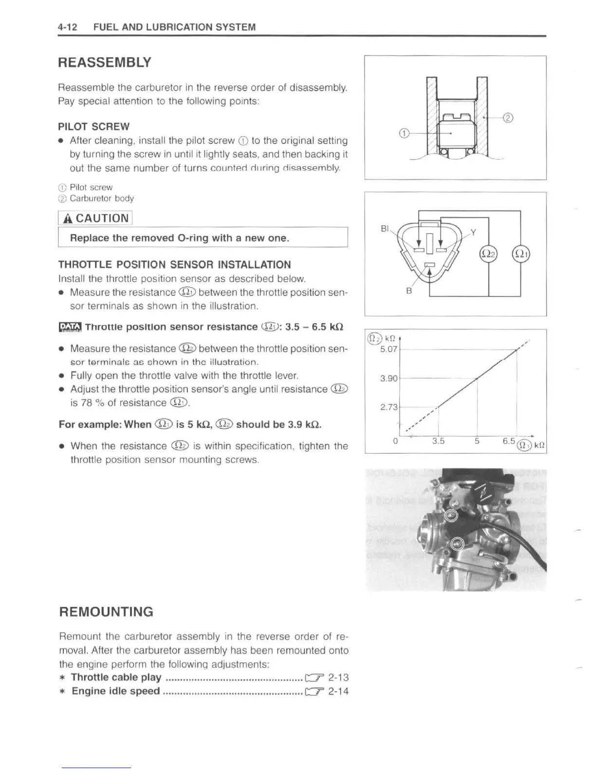
THROTTLE
POSITION SENSOR INSTALLATION
In
stall the throttle position sensor as described below.
•
Measure the resistance @ between the throttle position sen-
sor terminals as shown
in
the illustration.
~
Throttle positiOn
sensor
resistance
@:
3.5 - 6.5 IUl
•
Measure the resistance @ between the throttle position sen-
sor
terminals
ac
chown
in
the illustration.
• Fully open the throttle valve with the throttle lever.
•
Adjust the throttle position sensor's angle until resistance @
is
78
%
of
resistance @ .
For example: When @
is
5
1Ul
, @
should
be 3.9
1Ul
.
•
When
th
e resistance @
is
within specification, tighten the
throttle position sensor mounting screws.
REMOUNTING
Remount the carburetor assembly
in
the reverse order
of
re-
moval. After the carburetor assembly has been remounted onto
the engine perform the following adjustments:
*
Throttle
cable
play
................................................
c::::r
2-13
* Engine
idle
speed .................................................
c::::r
2-14
BI
®>
kll
5.07
3.
90
2.
73
o
B
y
--
-
.,,(
3
.5
5
http://www.motorcycle.in.th
 Loading...