FI SYSTEM AND INTAKE AIR SYSTEM 4-45
INSPECTION
• Lift and support the fuel tank with its prop stay. (4-51)
Turn the ignition switch OFF.
Check the STV actuator lead wire coupler for loose or
poor contacts.
Turn the ignition switch ON.
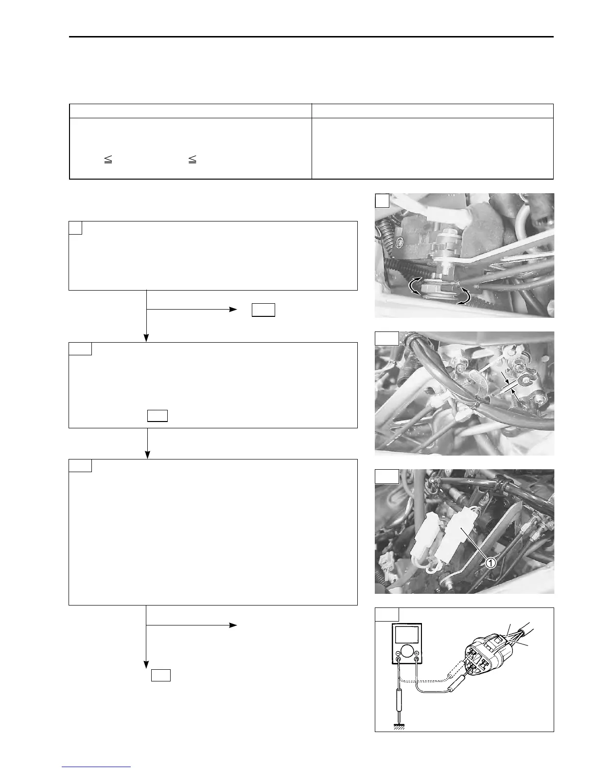
Check the movement of the STV actuator.
No
To 2-B (4-47)
Yes
Check the installation, the play and the slack of ST valve
control cables. (4-73)
If it is necessary, adjust the ST valve control cables.
(4-72)
If C28 code is indicated after adjusting the cable, perform
the section 3-A .
Turn the ignition switch OFF.
Disconnect the STVA position sensor lead wire coupler 1.
Turn the ignition switch ON.
Measure the voltage between the Red wire terminal and
B/Br wire terminal.
Position sensor input voltage: 4.5 – 5.5 V
++
++
+ Red –
- -
- -
- Ground
(
++
++
+ Red –
--
--
- B/Br
)
09900-25008: Multi circuit tester
Tester knob indication: Voltage (
)
No
Loose or poor contacts on
the ECM coupler.
Open or short circuit in the
Yes Red wire or B/Br wire.
To 4-A (Next page)
1
2-A
“C28” STV ACTUATOR CIRCUIT MALFUNCTION
DETECTED CONDITION POSSIBLE CAUSE
The operation signal does not reach the STV • STV actuator maladjusted.
actuator. • STV actuator circuit open or short.
STVA position sensor voltage low or high. • STVA motor malfunction.
0.2
Sensor Voltage 4.8 V • STVA position sensor malfunction.
(
without the above range.
)
3-A
“C24”, “C25”, “C26” or “C27” IGNITION SYSTEM MALFUNCTION
*Refer to the IGNITION SYSTEM for details. (7-20)
V
Ground
B/Br
Red
3-A
 Loading...


