ELECTRICAL SYSTEM 7-3
BATTERY
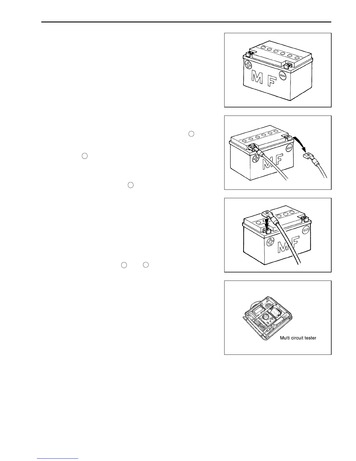
• The MF battery used in this vehicle does not require mainte-
nance as inspection of electrolyte level and replenishment of
water.
• No hydrogen gas is produced during normal charging of the
battery, but such gas may be produced when it is overcharged.
Therefore, do not bring fire near the battery while it is being
charged.
• Note that the charging system for the MF battery is different
from that of an ordinary battery. Do not replace with an ordi-
nary battery.
CONNECTING BATTERY
• When disconnecting terminals from the battery for disassem-
bly or servicing, be sure to disconnect the negative (
_
) termi-
nal first.
• When connecting terminals to the battery, be sure to connect
the positive (
+
) terminal first.
• If the terminal is found corroded, remove the battery, pour warm
water over it and clean with a wire brush.
• Upon completion of connection, apply grease lightly.
• Put a cover over the positive (
+
) terminal.
WIRING PROCEDURE
• Route the wire harness properly according to “WIRE HARNESS
ROUTING”. ( 8-14 – 16)
USING MULTI CIRCUIT TESTER
• Use the Suzuki multi-circuit tester (09900-25008).
• Use well-charged batteries in the tester.
• Be sure to set the tester to the correct testing range.
Using the tester
• Incorrectly connecting the
+
and
_
probes may cause the
inside of the tester to burnout.
• If the voltage and current are not known, make measurements
using the highest range.
• Reset the pocket tester to 0Ω before measuring each resis-
tance or after changing the resistance range.
• When measuring the resistance with the multi-circuit tester, also
measure the resistance with no-load. Sub-tract that resistance
from the resistance measured under load in order to get the
true resistance.
• When measuring the resistance with the multi-circuit tester, ∞
becomes 10.00MΩ and “1” flashes in the display.
• Check that no voltage is applied before making the measure-
ment. If voltage is applied, the tester may be damaged.
• After using the tester, turn the power off.
09900-25008: Multi-circuit tester
NOTE:
* When connecting the multi circuit tester, install fine copper wires
(O.D is below 0.5 mm) to the back side of the lead wire coupler
and connect the probes of tester to them.
* Use a fine copper wire, the outer diameter being below 0.5
mm, to prevent the rubber of the water proof coupler from dam-
age.
Measured
–
No load
=
Tr u e
[
resistance
][
resistance
]
[
resistance
]
 Loading...


