1H-6 Ignition System:
CKP Sensor Resistance
1) Remove the left side cover and left footrest
mudguard. Refer to “Exterior Parts Removal and
Installation in Section 9D (Page 9D-3)”.
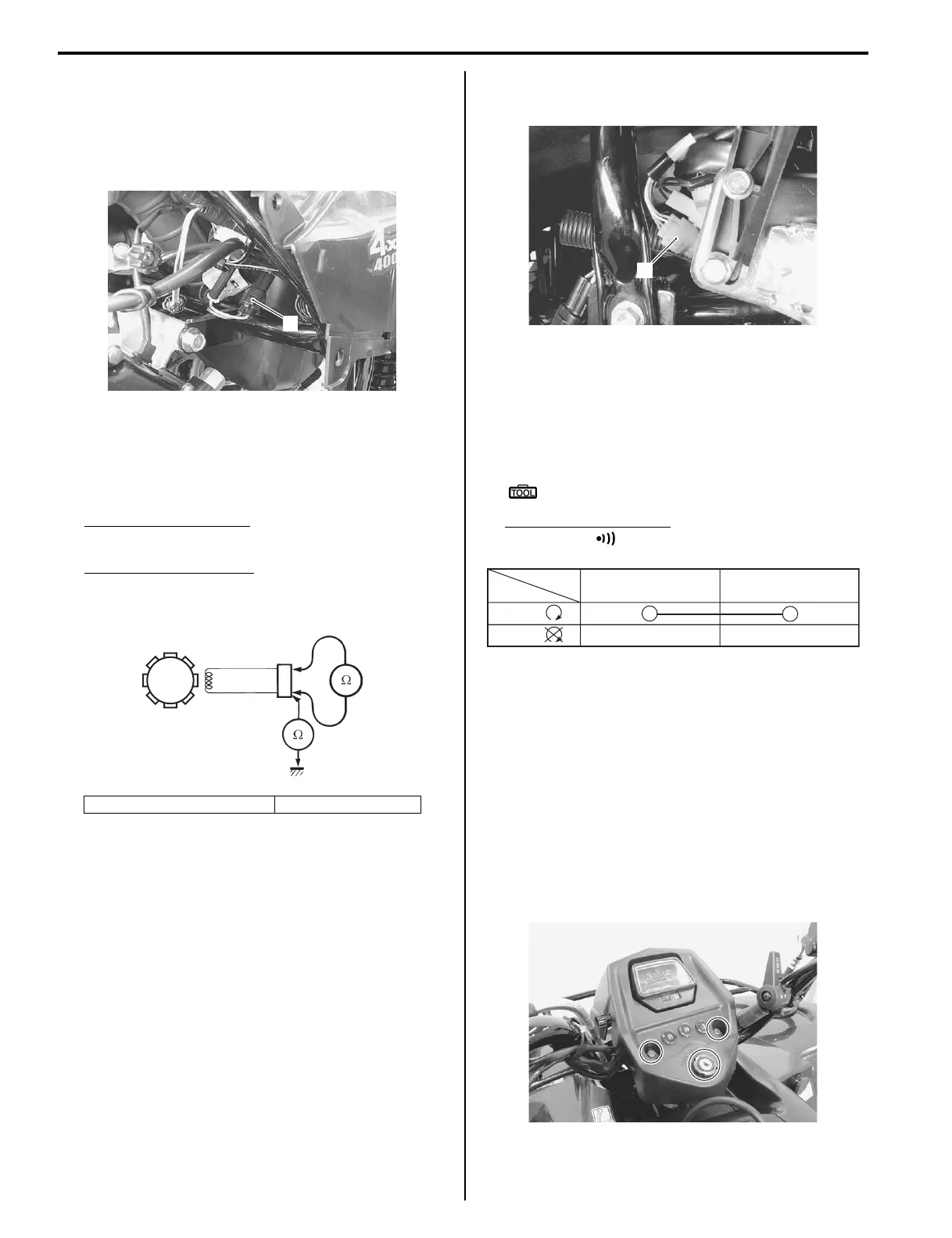
2) Disconnect the CKP sensor coupler (1).
3) Measure the resistance between the lead wires and
ground. If the resistance is not within the standard
range, replace the CKP sensor with a new one.
Refer to “CKP Sensor Removal and Installation
(Page 1H-6)”.
Tester knob indication
Resistance (Ω)
CKP sensor resistance
130 – 250 Ω (Bl – G)
∞ Ω (Bl – Ground)
4) After measuring the CKP sensor resistance, reinstall
the removed parts.
CKP Sensor Removal and Installation
B827H11806005
Refer to “Generator Removal and Installation in Section
1J (Page 1J-5)”.
Engine Stop Switch Inspection
B827H11806006
Inspect the engine stop switch in the following
procedures:
1) Turn the ignition switch OFF.
2) Remove the left inner fender. Refer to “Exterior Parts
Removal and Installation in Section 9D (Page 9D-
3)”.
3) Disconnect the handlebar switch coupler (1)
(Yellow).
4) Inspect the engine stop switch for continuity with a
tester.
If any abnormality is found, replace the handlebar
switch assembly with a new one. Refer to
“Handlebars Removal and Installation in Section 6B
(Page 6B-3)”.
Special tool
: 09900–25008 (Multi-circuit tester set)
Tester knob indication
Continuity ( )
5) After finishing the engine stop switch inspection,
reinstall the removed parts.
Ignition Switch Inspection
B827H11806007
Refer to “Ignition Switch Inspection in Section 9C
(Page 9C-3)”.
Ignition Switch Removal and Installation
B827H11806008
Removal
1) Remove the ignition switch from the speedometer
cover.
2) Remove the left inner fender. Refer to “Exterior Parts
Removal and Installation in Section 9D (Page 9D-
3)”.
2. CKP sensor coupler 3. CKP sensor
1
I827H1180008-01
3
2
I718H1180008-02
1
I827H1180009-01
O O/W
Color
Position
OFF
RUN
()
()
I831G1180009-01
I827H1180010-01
 Loading...


