Lighting Systems: 9B-7
Dimmer Switch Inspection
B827H19206014
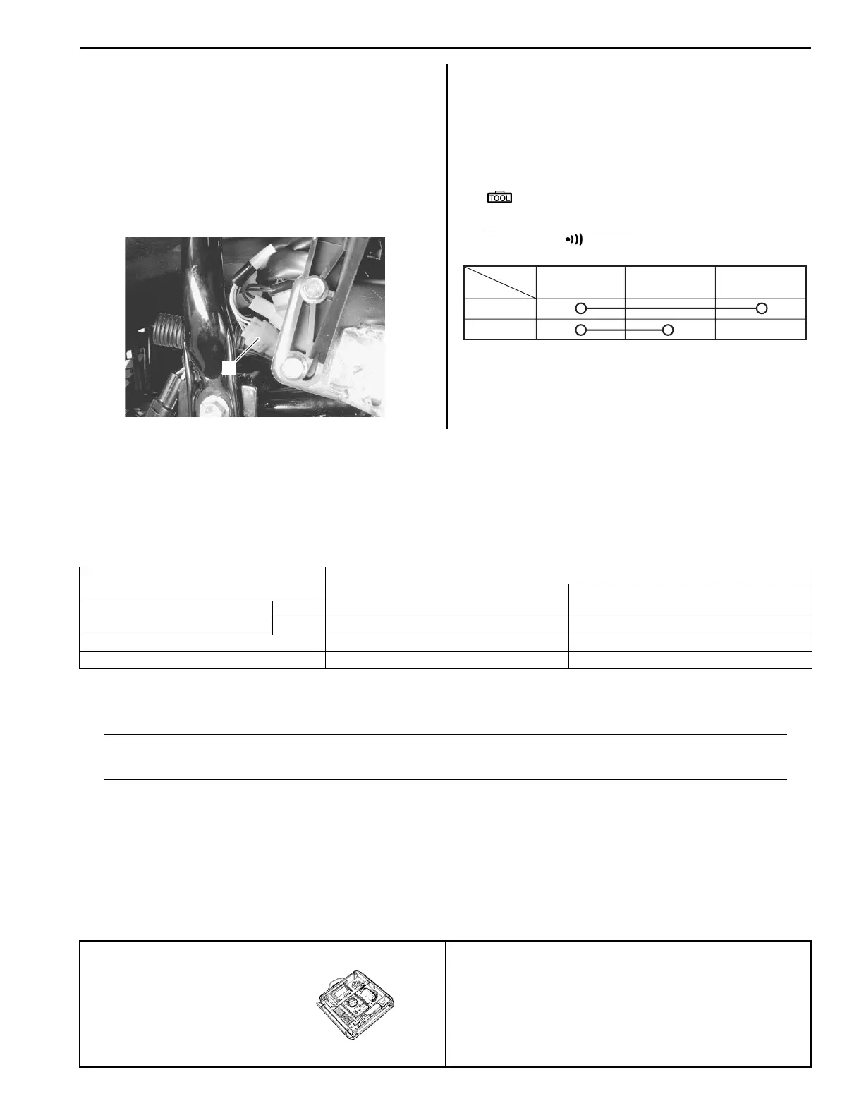
Inspect the dimmer switch in the following procedures:
1) Turn the ignition switch OFF.
2) Remove the left inner fender. Refer to “Exterior Parts
Removal and Installation in Section 9D (Page 9D-
3)”.
3) Disconnect the handlebar switch coupler (1)
(Yellow).
4) Inspect the dimmer switch for continuity with the
tester.
If any abnormality is found, replace the handlebar
switch assembly with a new one.
Refer to “Handlebars Removal and Installation in
Section 6B (Page 6B-3)”.
Special tool
: 09900–25008 (Multi-circuit tester set)
Tester knob indication
Continuity ( )
5) After finishing the dimmer switch inspection, reinstall
the removed parts.
Specifications
Service Data (LT-A400/F, LT-F400/F)
B827H19207001
Wattage
Unit: W
Tightening Torque Specifications
B827H19207002
NOTE
The specified tightening torque is also described in the following.
“Front Side Reflector Construction (Page 9B-2)”
Reference:
For the tightening torque of fastener not specified in this section, refer to “Tightening Torque List (LT-A400/F) in
Section 0C (Page 0C-9)”.
Special Tools and Equipment
Special Tool
B827H19208001
1
I827H1180009-01
Position
Color
Gr W Y
HI
LO
I831G1920027-01
Item
Specification
P 24, 28, 33 P-17
Headlight
HI 35 x 2 ←
LO 35 x 2 ←
Brake light/Taillight 21/5 ←
Reversing light — 21
09900–25008
Multi-circuit tester set
)(Page 9B-6) / )(Page 9B-
7)
 Loading...


