4A-13 Brake Control System and Diagnosis:
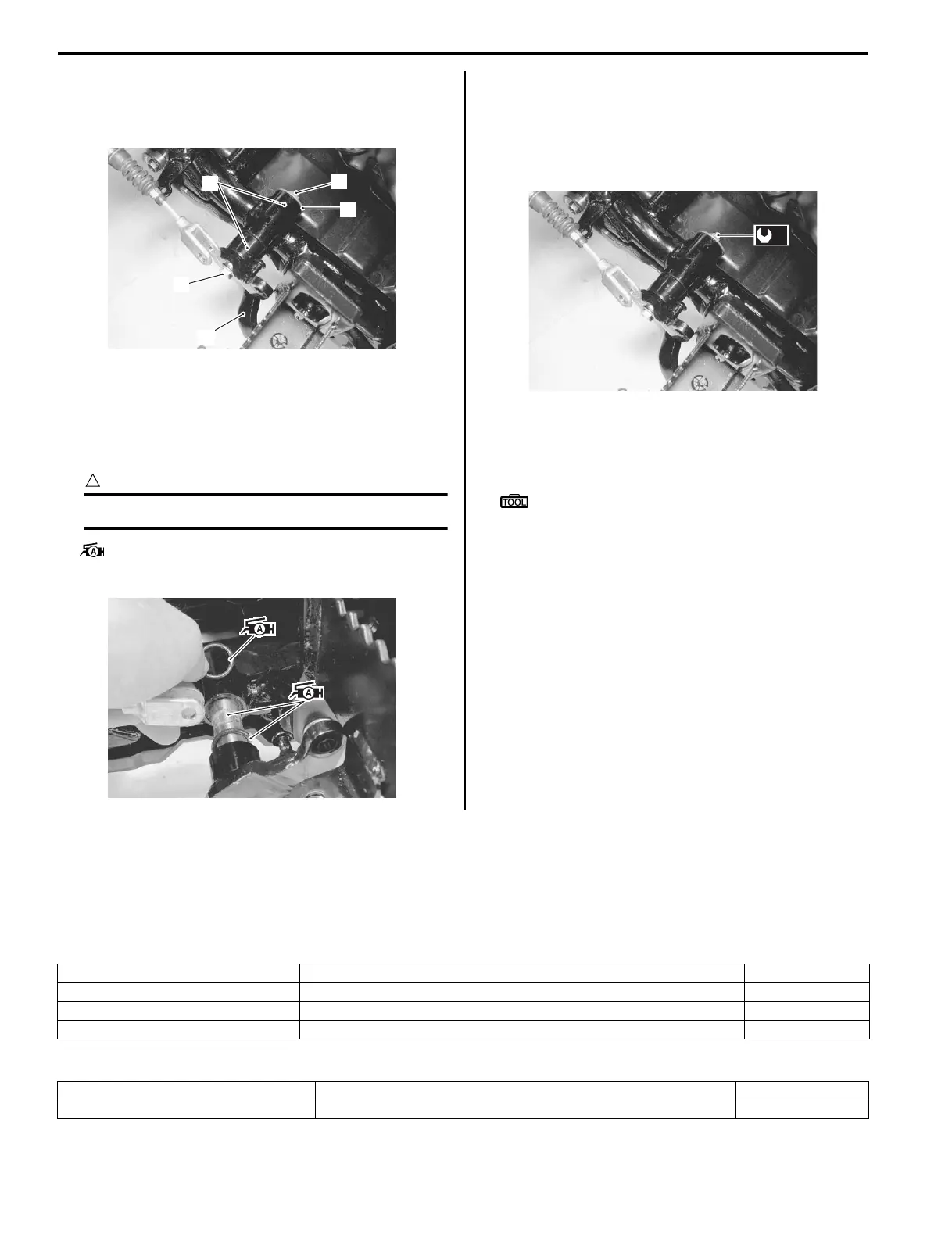
4) Remove the nut (6), washer (7), O-rings (8) and bolt
(9).
5) Remove the rear brake pedal (10).
Installation
Install the rear brake pedal in the reverse order of
removal. Pay attention to the following points:
• Apply grease to the O-rings and brake pedal pivot.
CAUTION
!
Replace the O-rings with new ones.
: Grease 99000–25010 (SUZUKI SUPER
GREASE A or equivalent)
• Tighten the rear brake pedal pivot nut to the specified
torque.
Tightening torque
Rear brake pedal pivot nut (a): 12 N·m (1.2 kgf-m,
8.5 lb-ft)
• Install the brake pedal spring and brake light switch
spring correctly. Refer to “Rear Brake Pedal
Construction (Page 4A-12)”.
Special tool
: 09920–20310 (Clutch spring hook)
• After installing the rear brake pedal, check the rear
brake pedal free travel. Refer to “Rear Brake Pedal /
Rear Brake (Parking Brake) Lever Inspection and
Adjustment in Section 0B (Page 0B-16)”.
Specifications
Service Data (LT-A400/F, LT-F400/F)
B827H14107001
Brake
Unit: mm (in)
Oil
6
7
8
9
10
I827H1410033-02
I827H1410034-01
(a)
I827H1410038-01
Item Standard Limit
Rear brake pedal free travel 20 – 30 (0.8 – 1.2) —
Front master cylinder bore 14.000 – 14.043 (0.5512 – 0.5529) —
Front master cylinder piston diam. 13.957 – 13.984 (0.5495 – 0.5506) —
Item Specification Note
Brake fluid type DOT 4
 Loading...


