6B-5 Steering / Handlebar:
• Apply grease to the parking brake cable end.
: Grease 99000–25010 (SUZUKI SUPER
GREASE A or equivalent)
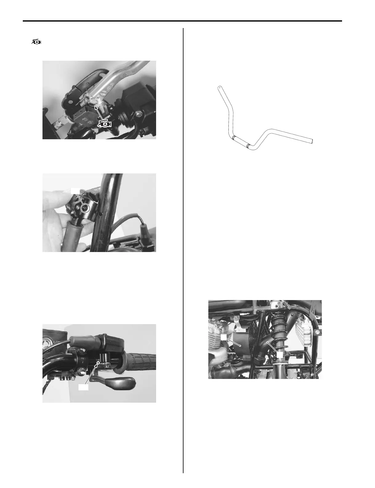
• Insert the projection “F” of the transfer lever into the
hole of the handlebars. (LT-A400F, LT-F400F)
LT-A400F, LT-F400F
• Install the right grip as the same manner of left grip.
• Install the front brake master cylinder. Refer to “Front
Brake Master Cylinder Assembly Removal and
Installation in Section 4A (Page 4A-8)”.
• Align the punch mark “G” on the handlebars with the
mating surface of the throttle lever case.
• Tighten the throttle lever case bolts.
Handlebars Inspection
B827H16206004
Refer to “Handlebars Removal and Installation
(Page 6B-3)”.
Inspect the handlebars for distortion or damage.
If any defects are found, replace the handlebars with a
new one.
Steering Shaft / Tie-rod Removal and
Installation
B827H16206005
Removal
1) Remove the front wheels. Refer to “Front / Rear
Wheel Removal and Installation in Section 2D
(Page 2D-3)”.
2) Remove the front fender. Refer to “Exterior Parts
Removal and Installation in Section 9D (Page 9D-
3)”.
3) Remove the cooling fan (1) and inlet cooling duct (2)
(LT-A400/F). Refer to “Cooling Fan Removal and
Installation in Section 1E (Page 1E-13)” and “V-belt
Cooling Duct Removal and Installation (LT-A400/F)
in Section 5A (Page 5A-6)”.
LT-A400F, LT-F400F
I827H1620014-01
“F”
I827H1620015-01
“G”
I827H1620016-01
I827H1620017-01
1
2
I827H1620018-01
 Loading...


