Engine Mechanical: 1D-1
Engine
Engine Mechanical
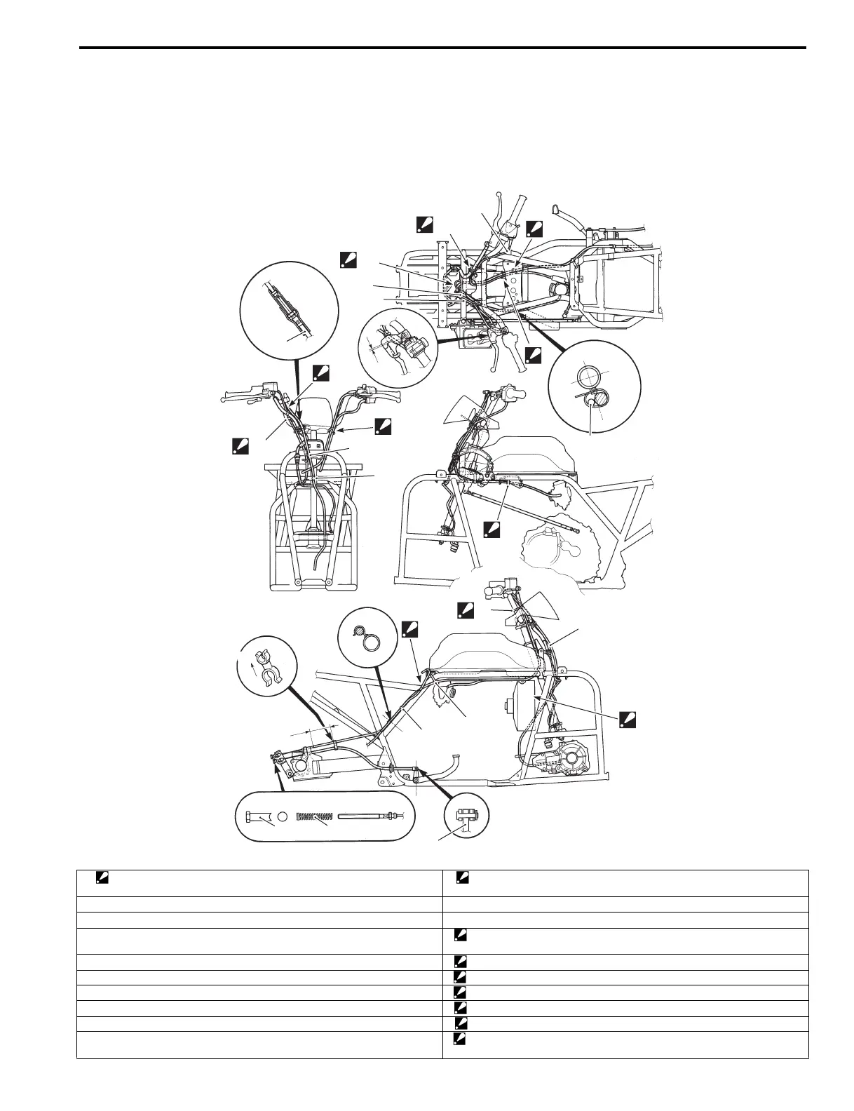
Schematic and Routing Diagram
Throttle Cable Routing Diagram
B827H11402001
“E”
“D”
4
5
6
6
“F”
“C”
“a”
12
2
“A”
1
“B”
2
3
UP
“b”
7
11
1
2
“G”
10
9
8
INSIDE
“H”
I827H1140304-02
1. Clamp
: Bind the front brake switch lead wire and throttle cable with the clamp.
12. Clamp
: Bind the starter cable with the clamp.
2. Transfer cable (LT-A400F, LT-F400F) “a”: 3 – 5 mm (0.1 – 0.2 in)
3. Clamp (LT-A400F, LT-F400F) “b”: 70 ± 10 mm (2.8 ± 0.4 in)
4. Throttle cable “A”: Pass the throttle cable into the concave side of the transfer lever holder.
(LT-A400F, LT-F400F)
5. Parking brake cable “B”: Pass the starter cable and rear brake cable to inside of the guide.
6. Starter cable “C”: Pass the parking brake cable to outside of the throttle cable.
7. Clamp “D”: Fix the rubber of throttle cable to the cable guide.
8. Brake adjuster nut “E”: Pass the speedometer cable to inside of the center hole.
9. Spring “F”: Pass the throttle cable and parking brake cable to inside of the guide.
10. Pin “G”: Pass the transfer cable inside of cooling fan bracket. (LT-A400F, LT-
F400F)
 Loading...


