9C-3 Combination Meter / Fuel Meter / Horn:
Installation
Install the speedometer in the reverse order of removal.
Pay attention to the following points:
• Rout the speedometer cable properly. Refer to
“Throttle Cable Routing Diagram in Section 1D
(Page 1D-1)”.
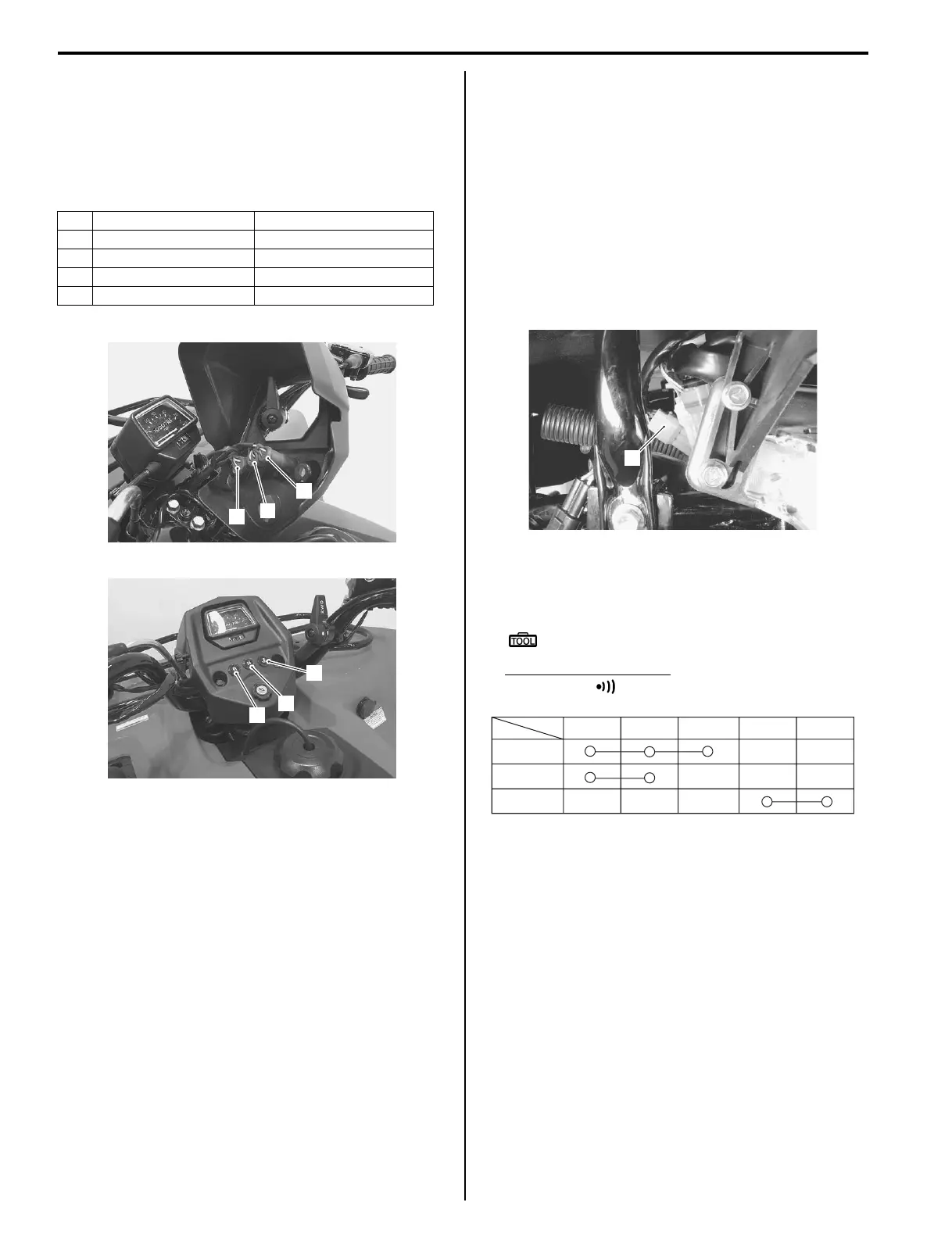
• Install the indicator lights in the proper arrangement.
Speedometer Disassembly and Assembly
B827H19306003
Refer to “Speedometer Removal and Installation
(Page 9C-2)”.
Disassembly
Disassemble the speedometer as shown in the
speedometer components. Refer to “Speedometer
Components (Page 9C-1)”.
Assembly
Assemble the speedometer as shown in the
speedometer components. Refer to “Speedometer
Components (Page 9C-1)”.
Speedometer light bulb / Indicator light bulb
Replacement
B827H19306016
Refer to “Speedometer Removal and Installation
(Page 9C-2)”.
Ignition Switch Inspection
B827H19306012
Inspect the ignition switch in the following procedures:
1) Remove the left inner fender Refer to “Exterior Parts
Removal and Installation in Section 9D (Page 9D-
3)”.
2) Disconnect the ignition switch coupler (1) (Green).
3) Inspect the ignition switch for continuity with a tester.
If any abnormality is found, replace the ignition
switch with a new one.
Special tool
: 09900–25008 (Multi-circuit tester set)
Tester knob indication
Continuity ( )
4) After finishing the ignition switch inspection, reinstall
the removed parts.
Ignition Switch Removal and Installation
B827H19306013
Refer to “Ignition Switch Removal and Installation in
Section 1H (Page 1H-6)”.
Wire color Lens
1 O/G – Bl/W Oil temperature
2 O/G – Bl/B Neutral
3 O/G – Bl/R Reverse
– Y – B/W High beam (P-17 only)
1
2
3
I827H1930007-02
1
2
3
I827H1930008-01
1
I827H1180011-01
Color
Position
R O Gr B/W B/Y
ON
LIGHT
OFF
I827H1930009-01
 Loading...


