3D-16 Propeller Shafts:
• Install the shim (2), drive bevel gear (3) and washer
(4).
• Hold the output shaft with the special tool.
Special tool
(A): 09930–73190 (Output shaft holder)
• Tighten the drive bevel gear nut to the specified
torque.
CAUTION
!
The removed drive bevel gear nut must be
replaced with a new one.
Tightening torque
Drive bevel gear nut (a): 100 N·m (10.0 kgf-m,
72.5 lb-ft)
• After the backlash and tooth contact have been
checked or adjusted, stake the nut with a center
punch.
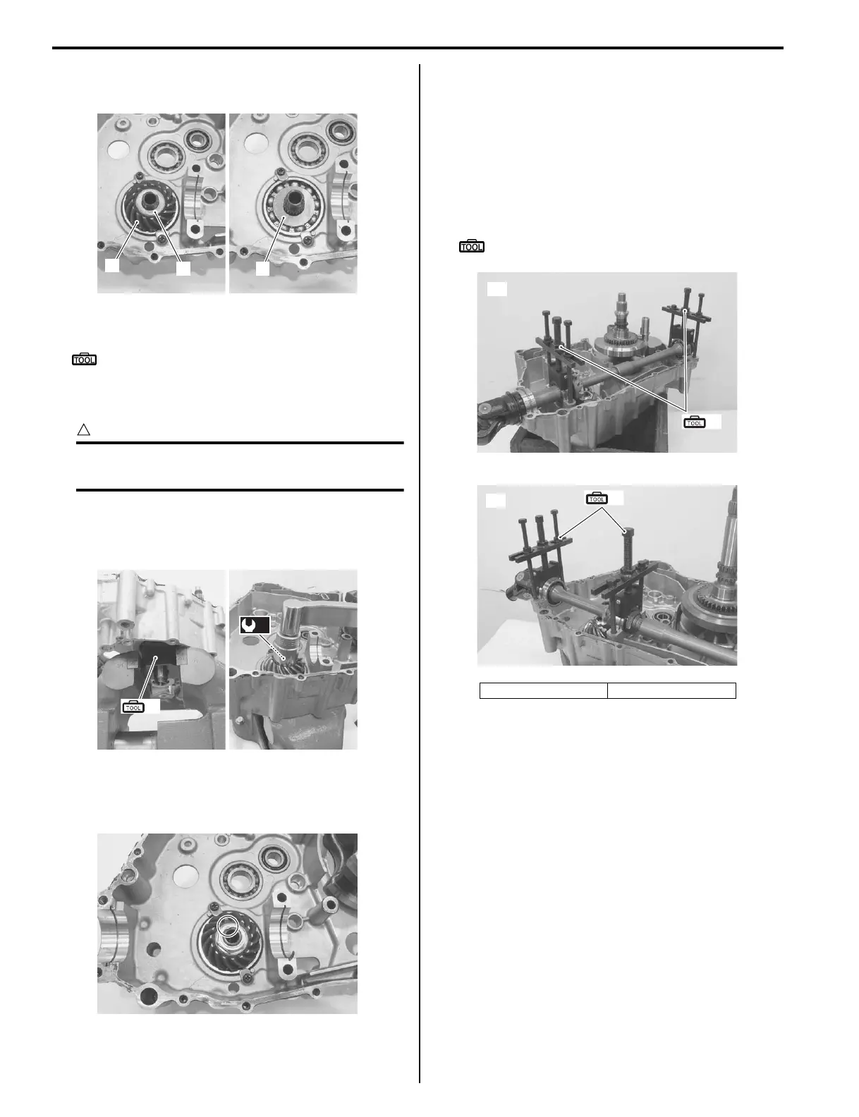
Driven and Drive Bevel Gear Shim Inspection
and Adjustment
B827H13406009
Refer to “Output Shaft Removal and Installation
(Page 3D-3)”.
Backlash
1) Place the rear output shaft on the left crankcase half
and hold bearings with the special tool.
Special tool
(A): 09921–21910 (Bearing holder)
2
3
4
I827H1340075-01
(a)
(A)
I827H1340076-01
I827H1340077-01
[A]: LT-A400/F [B]: LT-F400/F
(A)
[A]
I827H1340078-01
(A)
[B]
I827H1340079-01
 Loading...


