5B-13 Manual Transmission:
Gearshift Shaft Oil Seal Removal and
Installation (LT-A400/F)
B827H15206022
Removal
• Remove the generator cover. Refer to “Generator
Removal and Installation in Section 1J (Page 1J-5)”.
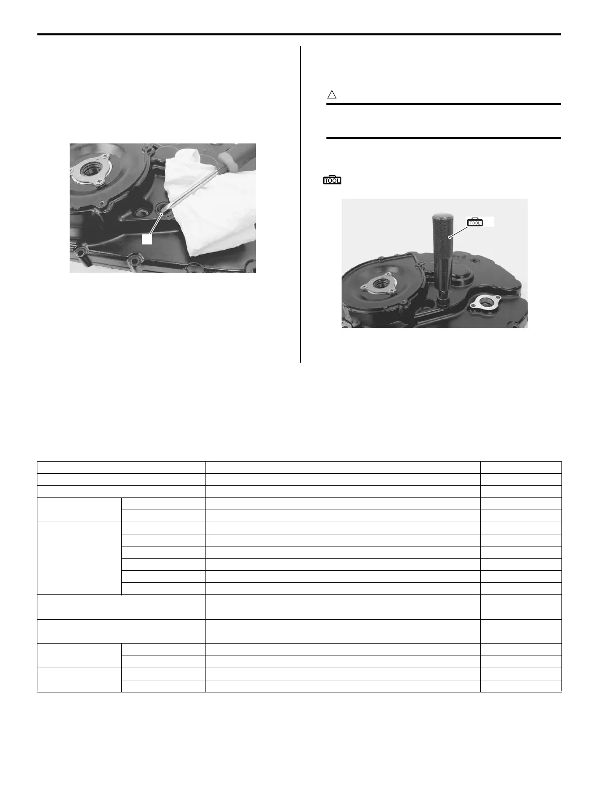
• Remove the gearshift shaft oil seal (1).
Installation
Install the oil seal in the reverse order of removal. Pay
attention to the following points:
CAUTION
!
The removed oil seal must be replaced with
new one.
• Install the oil seal with the special tool.
Special tool
(A): 09913–70210 (Bearing installer set)
• Install the generator cover. Refer to “Generator
Removal and Installation in Section 1J (Page 1J-5)”.
Specifications
Service Data (LT-F400/F)
B827H15207001
Drive train
Unit: mm (in) Except ratio
1
I827H1520041-01
(A)
I827H1520042-01
Item Standard Limit
Primary reduction ratio 2.392 (67/28) —
Secondary reduction ratio 1.133 (17/15) —
Final reduction
ratio
Front 3.600 (36/10) —
Rear 3.600 (36/10) —
Transmission
gear ratio
Low 3.083 (37/12) —
2nd 1.933 (29/15) —
3rd 1.388 (25/18) —
4th 1.095 (23/21) —
Top 0.913 (21/13) —
Reverse 2.833 (34/12) —
Transmission shift fork to groove
clearance
0.10 – 0.30 (0.004 – 0.012) 0.50 (0.020)
Reverse Shift fork to groove
clearance
0.10 – 0.30 (0.004 – 0.012) 0.50 (0.020)
Shift fork groove
width
Transmission 4.50 – 4.60 (0.178 – 0.181) —
Reverse 5.00 – 5.10 (0.197 – 0.201) —
Shift fork
thickness
Transmission 4.30 – 4.40 (0.169 – 0.173) —
Reverse 4.80 – 4.90 (0.189 – 0.193) —
 Loading...


