Transfer: 3C-22
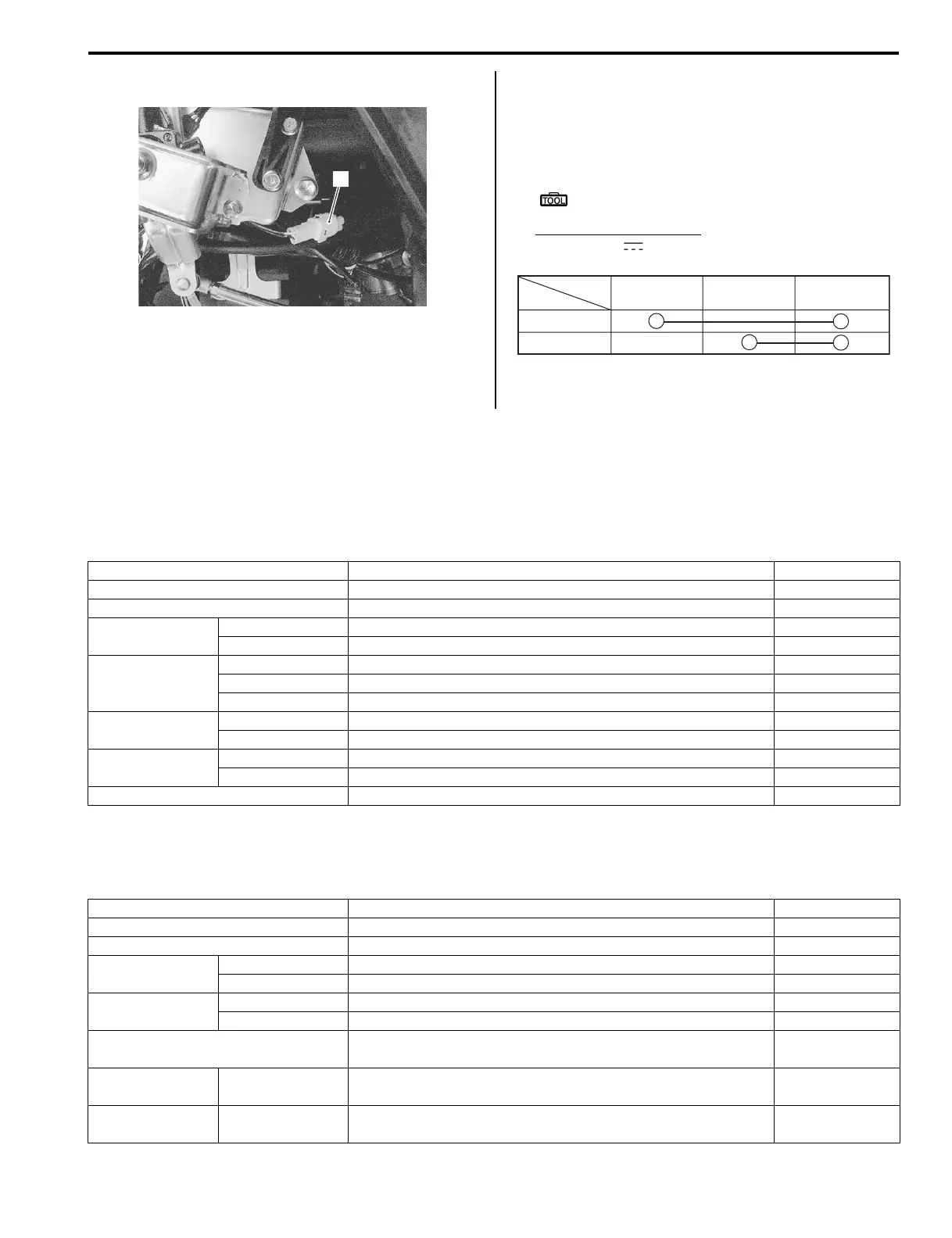
2) Disconnect the reverse switch coupler (1).
3) Inspect the reverse switch for continuity with the
taster. If any abnormality is found, replace the
reverse switch with a new one. Refer to “Transfer
Range Lever Removal and Installation (Page 3C-
20)”.
Special tool
: 09900–25008 (Multi-circuit tester set)
Tester knob indication
continuity ( )
4) After finishing the reverse switch inspection, reinstall
the removed parts.
Specifications
Service Data (LT-A400/F)
B827H13307001
Drive Train
Unit: mm (in) Except ratio
Service Data (LT-F400/F)
B827H13307002
Drive Train
Unit: mm (in) Except ratio
1
I827H1330060-01
YBBl
Color
Position
L and R
R
I827H1330061-02
Item Standard Limit
Automatic transmission ratio Variable change (2.938 – 0.813) —
Secondary reduction ratio 2.730 (42/19 x 21/17) —
Final reduction
ratio
Front 3.600 (36/10) —
Rear 3.600 (36/10) —
Transfer gear
ratio
Low 2.500 (40/16) —
High 1.375 (33/24) —
Reverse 2.125 (34/16) —
Shift fork groove
width
High/Low 5.50 – 5.60 (0.217 – 0.220) —
Reverse 5.50 – 5.60 (0.217 – 0.220) —
Shift fork
thickness
High/Low 5.30 – 5.40 (0.209 – 0.213) —
Reverse 5.30 – 5.40 (0.209 – 0.213) —
Gear shift fork to groove clearance 0.10 – 0.30 (0.004 – 0.012) —
Item Standard Limit
Primary reduction ratio 2.392 (67/28) —
Secondary reduction ratio 1.133 (17/15) —
Final reduction
ratio
Front 3.600 (36/10) —
Rear 3.600 (36/10) —
Transfer gear
ratio
Low 2.435 (35/13 x 19/21) —
High 1.296 (35/27) —
Transfer Shift fork to groove
clearance
0.10 – 0.30 (0.004 – 0.012) 0.50 (0.020)
Shift fork groove
width
Transfer 5.50 – 5.60 (0.217 – 0.220) —
Shift fork
thickness
Transfer 5.30 – 5.40 (0.209 – 0.213) —
 Loading...


