Transfer: 3C-6
• Hold the transfer driven gear with the special tool and
tighten the drive bevel gear nut to the specified
torque.
CAUTION
!
The removed drive bevel gear nut must be
replaced with a new one.
Special tool
(A): 09920–53740 (Clutch sleeve hub holder)
Tightening torque
Drive bevel gear nut (a): 100 N·m (10.0 kgf-m,
72.5 lb-ft)
NOTE
After the backlash and tooth contact have
been checked or adjusted, stake the nut with
a center punch.
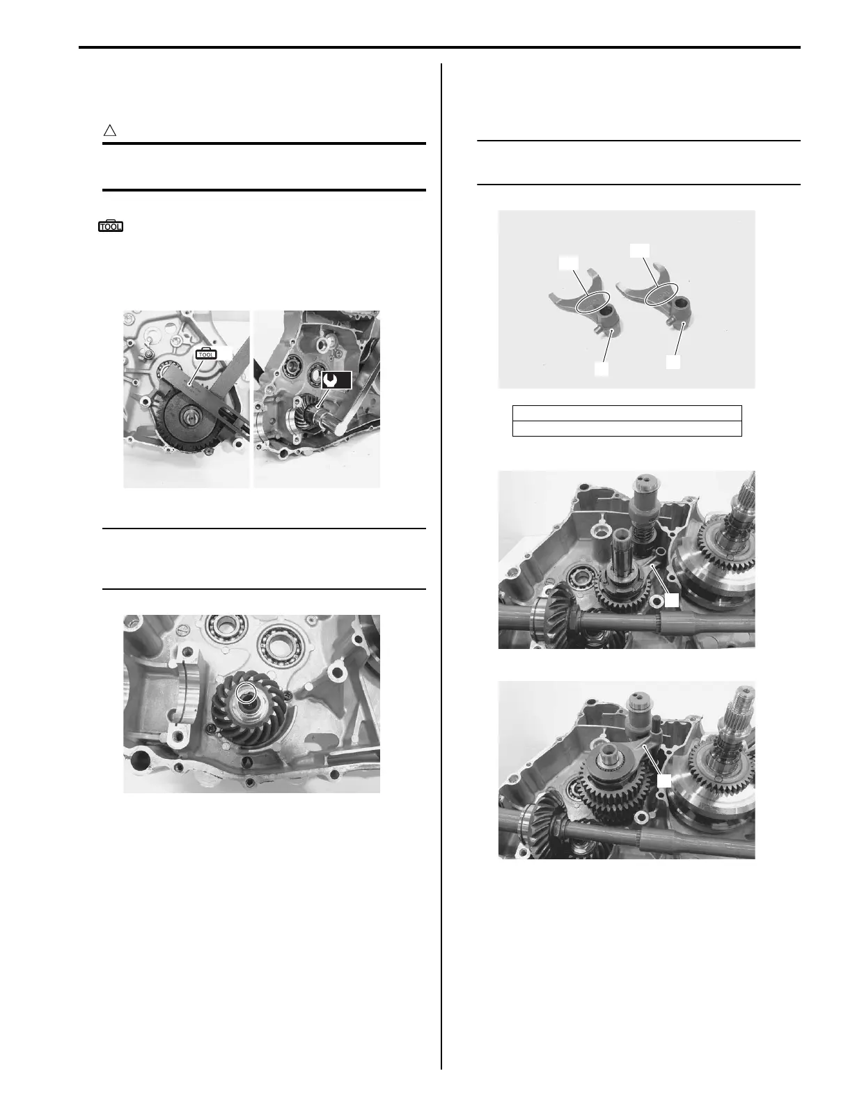
• Install the transfer gearshift cam assembly.
• Install the gearshift fork (5), reverse gearshift fork (6)
and transfer counter shaft assembly. Refer to
“Transfer Construction (LT-A400/F) (Page 3C-8)”.
NOTE
Each gearshift fork has own embossed
letters “A” or “B”.
• Install the reverse idle gear assembly. Refer to
“Transfer Construction (LT-A400/F) (Page 3C-8)”.
• Assemble the engine. Refer to “Engine Bottom Side
Assembly in Section 1D (Page 1D-43)”.
• Remount engine assembly. Refer to “Engine
Assembly Installation in Section 1D (Page 1D-9)” and
“Engine Top Side Assembly in Section 1D (Page 1D-
13)”.
(A)
(a)
I827H1330013-01
I827H1330014-01
“A”: 44D-TM (for high/low gears)
“B”: 44D-TL (for reverse gear)
5
6
“A”
“B”
I827H1330015-01
5
I827H1330016-01
6
I827H1330017-01
 Loading...


