1A-49 Engine General Information and Diagnosis:
P0115-H (Use of SDS)
Step Action Yes No
1 1) Turn the ignition switch OFF.
2) Remove the right air cleaner box. Refer to “Air Cleaner
Element Removal and Installation in Section 1D
(Page 1D-6)”.
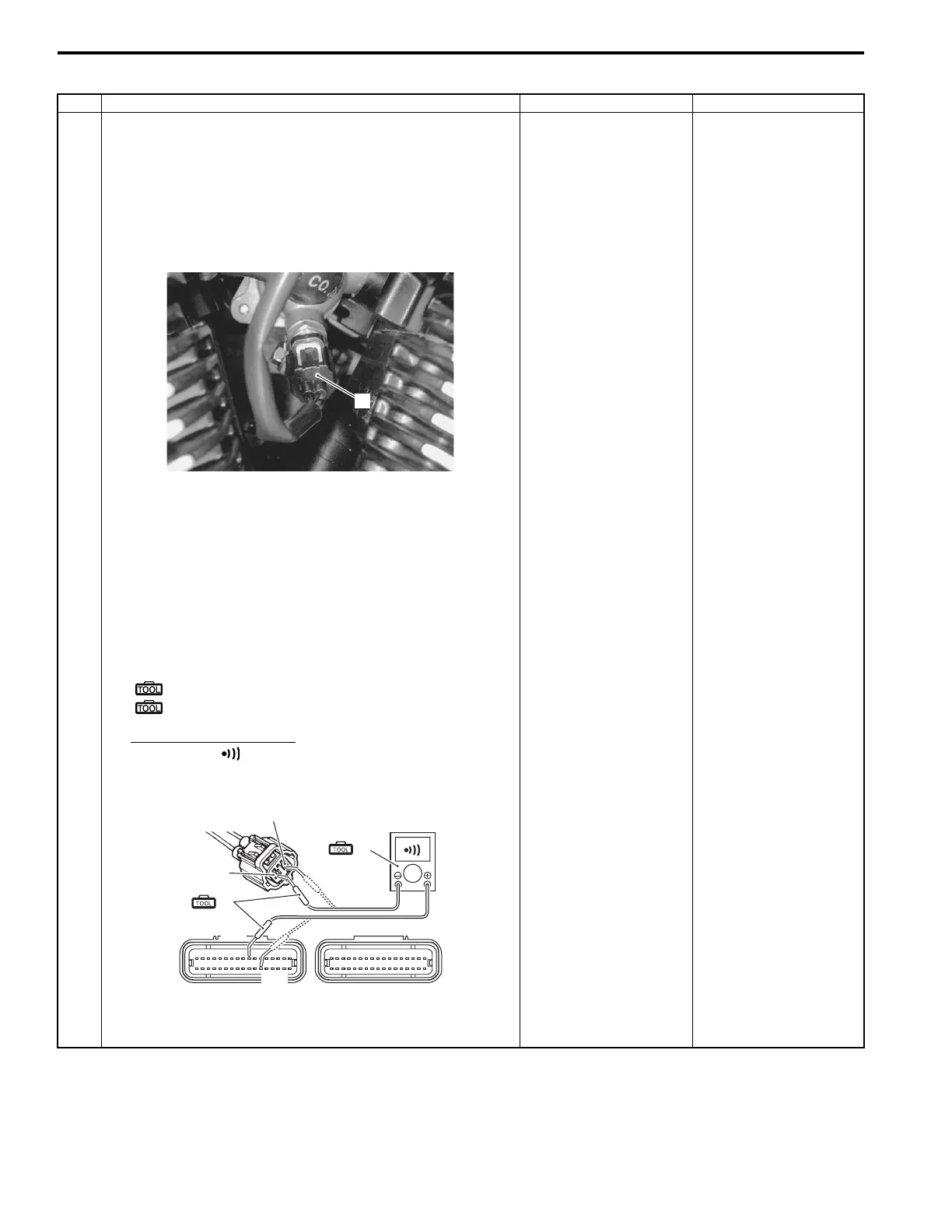
3) Check the ECT sensor coupler (1) for loose or poor
contacts.
If OK, then check the ECT sensor lead wire continuity.
4) Disconnect the ECT sensor coupler.
5) Disconnect the ECM coupler. Refer to “ECM Removal
and Installation in Section 1C (Page 1C-1)”.
6) Insert the needle pointed probes to the lead wire coupler.
7) Check the continuity between the B/Bl wire “A” and
terminal “10”.
Also, check the continuity between the B/Br wire “B” and
terminal “29”.
Special tool
(A): 09900–25008 (Multi-circuit tester set)
(B): 09900–25009 (Needle pointed probe set)
Tester knob indication
Continuity ( )
ECM couplers (Harness side)
Is the continuity and voltage OK?
Go to Step 2. B/Bl or B/Br wire open.
1
I822H1110033-01
(Black)
(Gray)
(A)
(B)
“10”
“29”
“A”
“B”
I822H1110034-01

 Loading...