EasyManuals Logo

Suzuki VLR1800 Service Manual

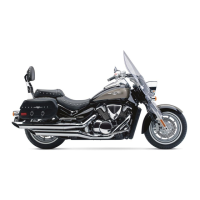
Suzuki VLR1800
624 pages
To Next Page IconTo Next Page
To Previous Page IconTo Previous Page
Page #73 background imageLoading...
Page #73 background image
Engine General Information and Diagnosis: 1A-4
Schematic and Routing Diagram
FI System Wiring Diagram
B822H11102001
N
1
2
3
4
5
10 A
15 A
15 A 30 A
15 A
10 A
ECM
14
43
16
48
47
33
39
* 65
17
31
21
8
11
6
20
26
27
22
29
5
4
3
10
9
G/W
B/G
G/Bl
G/R
Gr/W
O/W
Gr/B
Y/R
Dbr
51
W/Bl
68
Y
50
B
49
G
44
59
23
42
60
* 12
* 15
36
53
35
34
19
18
2
1
52
66
67
R/Y
Bl
Y/G
B/Y
W/G
W/Bl
Lbl
W
Dbr
Lg
B/W
B/W
B/W
P/W
W/B
G
B/Lg
P
Y/B
R/Bl
P/B
Y/W
G/B
Bl/P
B/Bl
B/Br
B/R
R/B
R
Dg
B
Y
Combination meter
CKPS
TPS
IG switch signal
STPS
IAPS #1
IAPS #2
ECTS
IATS
TOS
EXCVA
Cooling fan relay
FP
Side-stand relay
IG switch
PAIR control
solenoid
valve
Battery
EVAP system purge
control solenoid valve
GP
switch
Starter relay
Starter
motor
ISC valve
STVA
Starter button
Side-stand
switch
Headlight
relay
Ignition coil
M
Cooling fan motor
Fuel injector
FP relay
#1
#1
#2
#2
Engine stop
switch
M
(Except for E-03, 28)
O2S
Clutch
lever
position
switch
Neutral
indicator
light
(Except for
E-03, 28)
Headlight
* 12, 15 ..... Except for E-03, 28
* 65 ........... E-33 only
I822H1110003-05

Table of Contents

Questions and Answers:

Question and Answer IconNeed help?

Do you have a question about the Suzuki VLR1800 and is the answer not in the manual?

Suzuki VLR1800 Specifications

General IconGeneral
ManufacturerSuzuki
ModelVLR1800
Compression Ratio10.5:1
Fuel SystemFuel injection
StarterElectric
Transmission5-speed
CategoryCruiser
Displacement1783 cc
IgnitionElectronic ignition (Transistorized)
Final DriveShaft
Front SuspensionTelescopic, coil spring, oil damped
Rear SuspensionLink type, coil spring, oil damped
Rear BrakesSingle disc
Ground Clearance140 mm
Seat Height705 mm

Related product manuals