Manual Transmission: 5B-13
Installation
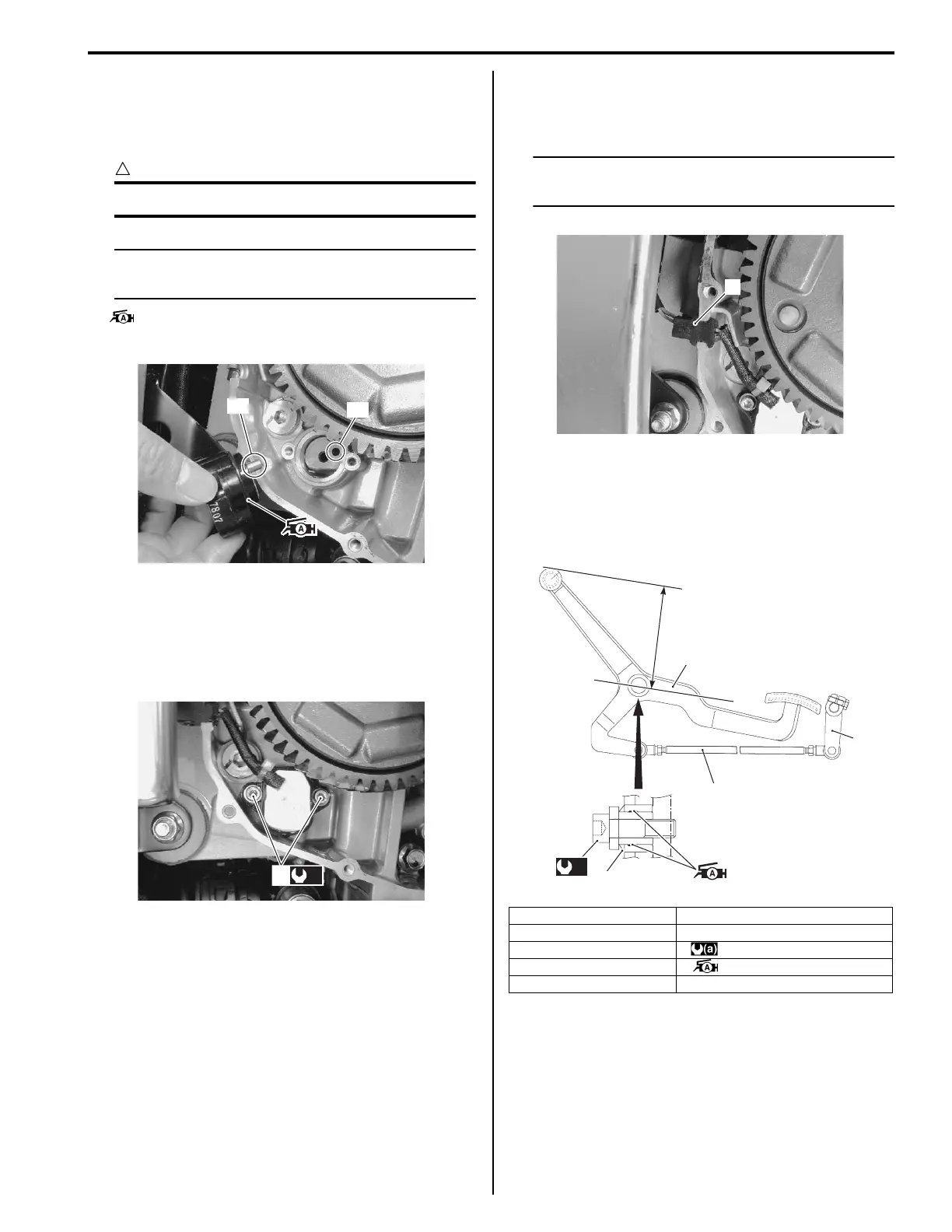
Install the gear position switch in the reverse order of
removal. Pay attention to the following points:
• Apply grease to the O-ring.
CAUTION
!
Replace the O-ring with a new one.
NOTE
Align the gear position switch pin “A” with
the gearshift cam hole “B”.
: Grease 99000–25010 (SUZUKI SUPER
GREASE A or equivalent)
• Tighten the gear position switch bolts (1) to the
specified torque.
Tightening torque
GP switch mounting bolt (a): 6.5 N·m (0.65 kgf-m,
4.5 lb-ft)
• Route the gear position switch lead wire. Refer to
“Wiring Harness Routing Diagram in Section 9A
(Page 9A-7)”.
NOTE
Be sure that the grommet (2) is set to the
crankcase.
• Install the clutch cover. Refer to “Clutch Installation in
Section 5C (Page 5C-6)”.
Gearshift Lever Construction
B822H15206009
“A”
“B”
I822H1520041-01
(a)
1
I822H1520043-02
1. Gearshift lever “A”: Footrest top surface
2. Gearshift link arm “a”: 115 – 125 mm (4.5 – 4.9 in)
3. Gearshift link rod : 50 N⋅m (5.0 kgf-m, 36.0 lb-ft)
4. Gearshift lever bolt : Apply grease.
5. Wave washer
2
I822H1520044-02
“a”
1
3
2
“A”
5
(a)
4
I822H1520045-06

 Loading...