Engine Electrical Devices: 1C-4
• Apply engine coolant to the O-ring (3) and Install the
thermostat case (4).
CAUTION
!
Use a new O-ring (3) to prevent engine
coolant leakage.
• Tighten the thermostat case mounting bolt (5).
• Tighten the water hose clamp screw (6) to the
specified torque.
Tightening torque
Water hose clamp screw (b): 1.5 N·m (0.15 kgf-m,
1.0 lb-ft)
ECT Sensor Inspection
B822H11306009
Refer to “DTC “C15” (P0115-H/L): ECT Sensor Circuit
Malfunction in Section 1A (Page 1A-47)”.
Inspect the ECT sensor in the following procedures:
1) Remove the ECT sensor. Refer to “ECT Sensor
Removal and Installation (Page 1C-3)”.
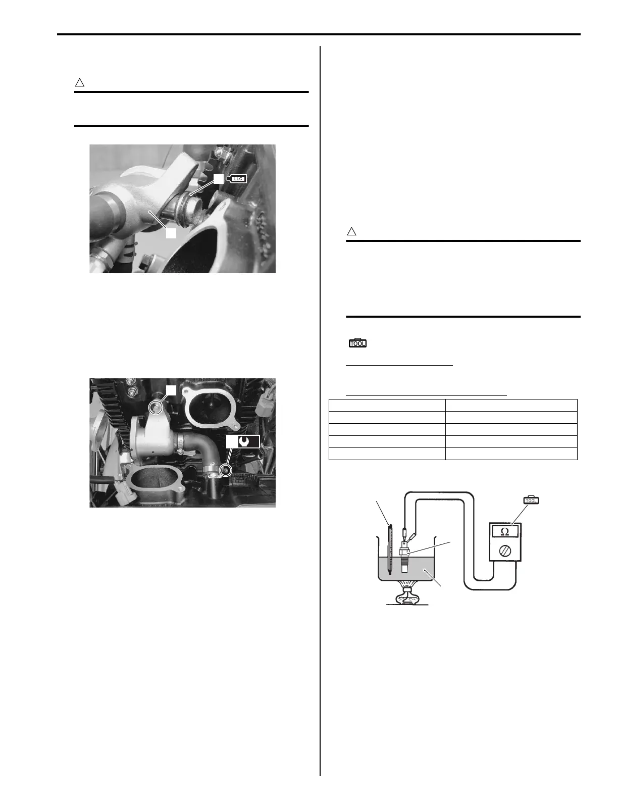
2) Connect the ECT sensor (1) to a circuit tester and
place it in the oil (2) contained in a pan, which is
placed on a stove.
3) Heat the oil to raise its temperature slowly and read
the column thermometer (3) and the ohmmeter.
If the ECT sensor ohmic valve does not change in
the proportion indicated, replace it with a new one.
CAUTION
!
• Take special care when handling the ECT
sensor. It may cause damage if it gets an
excessive sharp impact.
• Do not contact the ECT sensor and the
column thermometer with a pan.
Special tool
(A): 09900–25008 (Multi-circuit tester set)
Tester knob indication
Resistance (Ω)
Temperature sensor specification
4) Install the ECT sensor. Refer to “ECT Sensor
Removal and Installation (Page 1C-3)”.
3
4
I822H1130009-02
5
(b)
6
I822H1130010-02
Temperature Standard resistance
20 °C (68 °F) Approx. 2.45 kΩ
50 °C (122 °F) Approx. 0.811 kΩ
80 °C (176 °F) Approx. 0.318 kΩ
110 °C (230 °F) Approx. 0.142 kΩ
(A)
2
1
3
I718H1130014-01

 Loading...