Engine General Information and Diagnosis: 1A-58
Troubleshooting
CAUTION
!
When using the multi-circuit tester, do not strongly touch the terminal of the ECM coupler with a
needle pointed tester probe to prevent terminal damage.
NOTE
After repairing the trouble, clear the DTC using SDS tool. Refer to “Use of SDS Diagnosis Reset
Procedures (Page 1A-14)”.
C23 (Use of mode select switch)
Step Action Yes No
1 1) Turn the ignition switch OFF.
2) Remove the right frame cover. Refer to “Exterior Parts
Removal and Installation in Section 9D (Page 9D-3)”.
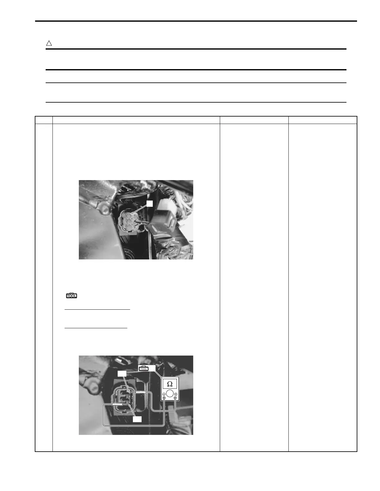
3) Check the TO sensor coupler (1) for loose or poor
contacts.
If OK, then measure the TO sensor resistance.
4) Measure the resistance between terminal “A” and
terminal “B”.
Special tool
(A): 09900–25008 (Multi-circuit tester set)
Tester knob indication
Resistance (Ω)
TO sensor resistance
16.5 – 22.3 kΩ
(Terminal “A” – Terminal “B”)
Is the resistance OK?
Go to Step 2. Replace the TO sensor
with a new one. Refer to
“TO Sensor Removal
and Installation in
Section 1C (Page 1C-
5)”.
1
I822H1110046-01
(A)
“B”
“A”
I822H1110047-03

 Loading...