Engine General Information and Diagnosis: 1A-96
P1658 (Use of SDS)
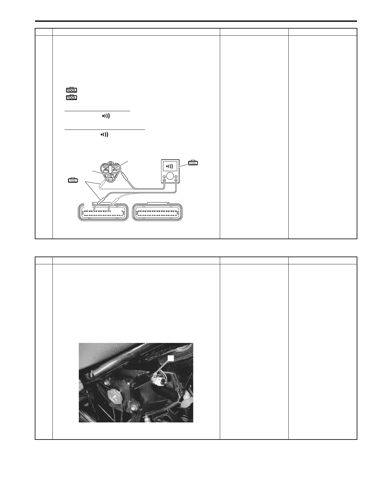
1 6) Disconnect the ECM coupler.
7) Check the continuity between Y wire “A” and terminal
“5”.
Also, check the continuity between R wire “C” and
terminal “11”.
Special tool
(A): 09900–25008 (Multi-circuit tester set)
(B): 09900–25009 (Needle pointed probe set)
Tester knob indication
Continuity ( )
EXCVA lead wire continuity
Continuity ( )
ECM couplers (Harness side)
Is the continuity OK?
Go to Step 2 and go to
Step 4.
R or Y wire open, or Y
wire shorted to ground.
Step Action Yes No
(A)
“5”
“11”
(B)
“A”
“C”
I822H1110109-01
Step Action Yes No
1 1) Turn the ignition switch OFF.
2) Remove the right frame cover (All models) and EVAP
canister (For E-33). Refer to “Exterior Parts Removal
and Installation in Section 9D (Page 9D-3)” (All models)
and “Evaporative Emission Control System Removal
and Installation (Only for E-33) in Section 1B (Page 1B-
13)”.
3) Check the EXCVA motor coupler (1) for loose or poor
contacts.
Is the contacting OK?
Go to Step 6. Loose or poor contacts
on the EXCV motor
coupler.
1
I822H1110110-01

 Loading...