Engine Mechanical: 1D-14
Special tool
: 09930–11950 (Torx wrench)
Tightening torque
TP sensor mounting screw: 3.5 N·m (0.35 kgf-m,
2.5 lb-ft)
NOTE
Make sure the throttle valve open or close
smoothly. If the TP sensor adjustment is
necessary, refer to “TP Sensor Adjustment in
Section 1C (Page 1C-2)”.
• Apply thin coat of the engine oil to the new cushion
seal (4) and O-ring (5).
CAUTION
!
Replace the cushion seal and O-ring with the
new ones.
• Install the fuel injector (6) by pushing it straight to the
delivery pipe (7).
CAUTION
!
Never turn the injector while pushing it.
NOTE
Align the coupler “E” of the injector with
boss “F” of the delivery pipe.
• Install the fuel delivery pipe assembly (7) to the
throttle body assembly.
CAUTION
!
Never turn the fuel injectors while installing
them.
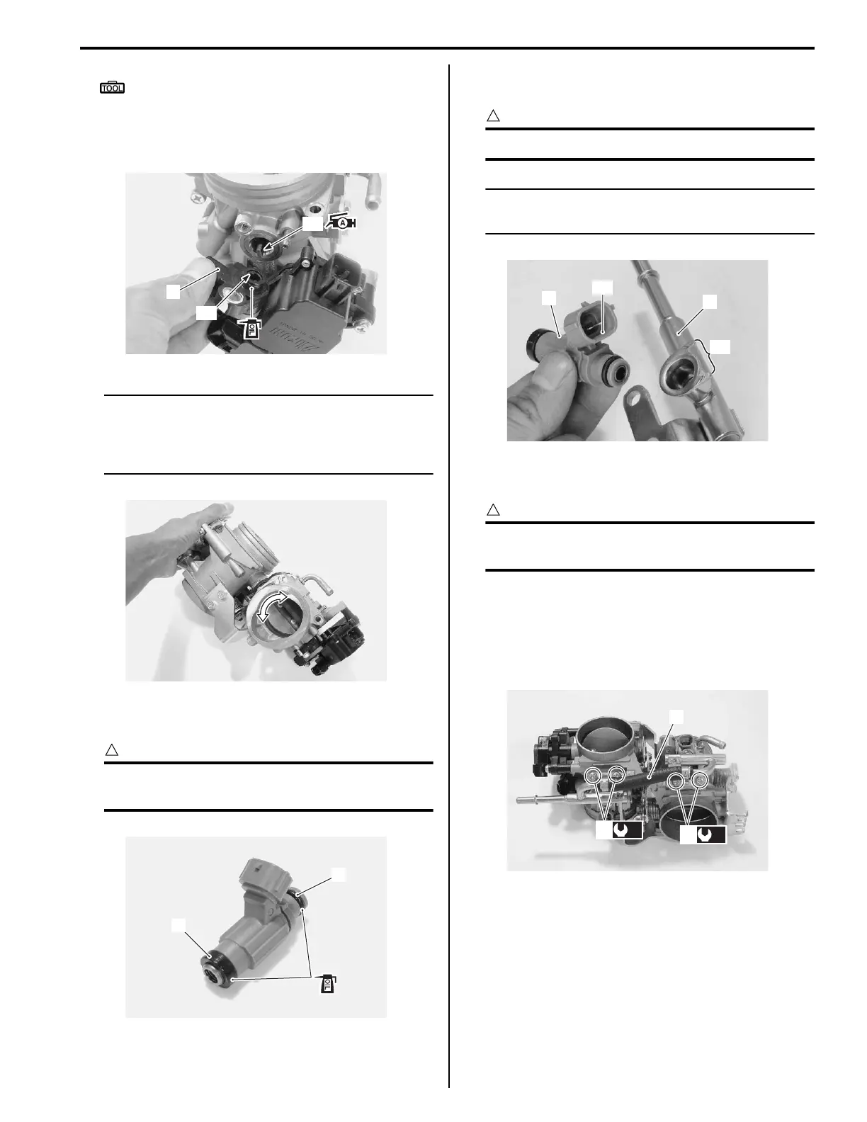
• Tighten the fuel delivery pipe mounting screws (8) to
the specified torque.
Tightening torque
Fuel delivery pipe mounting screw (b): 5 N·m (0.5
kgf-m, 3.5 lb-ft)
2
“C”
“D”
I822H1140027-02
I822H1140028-01
4
5
I822H1140029-02
6
7
“E”
“F”
I822H1140030-02
7
(b)
8
(b)
8
I822H1140031-03

 Loading...