1D-69 Engine Mechanical:
• Apply a small quantity of thread lock to the bolts and
tighten them.
: Thread lock cement 99000–32110
(THREAD LOCK CEMENT SUPER 1322 or
equivalent)
Gearshift Fork / Gearshift Cam
• Install the gearshift component parts. Refer to
“Transmission Removal in Section 5B (Page 5B-3)”.
Oil Pump
Install the oil pump assembly (1). Refer to “Oil Pump
Removal and Installation in Section 1E (Page 1E-9)”.
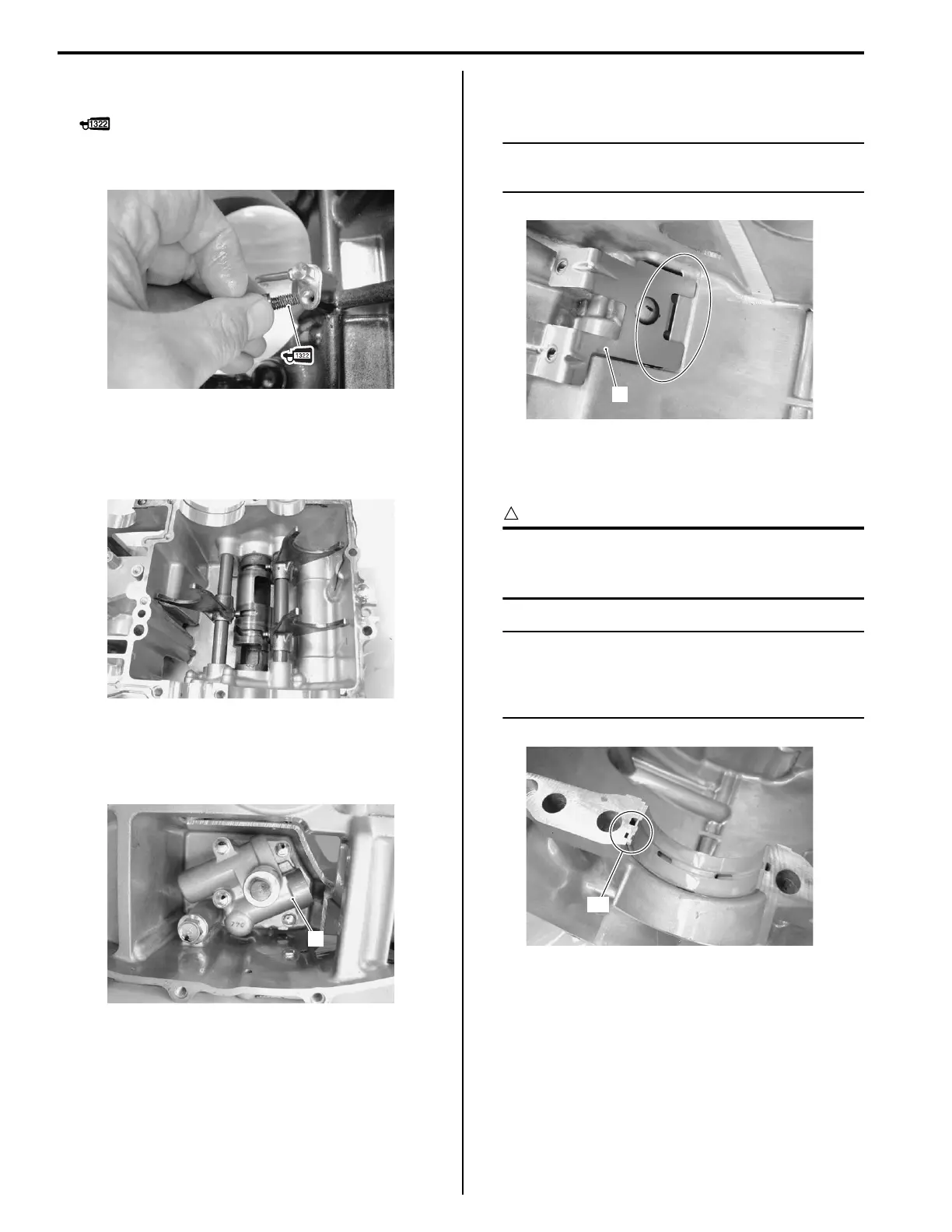
Balancer Shaft / Crankshaft
• Install the oil separator (1).
NOTE
Align the oil separator claw with the lower
crankcase hole.
• When fitting the crankshaft journal bearings to the
upper and lower crankcases, be sure to fix the stopper
part “A” first and press the other end.
CAUTION
!
Do not touch the bearing surfaces with your
hands. Grasp by the edge of the bearing
shell.
NOTE
Inspect and select the crankshaft journal
bearing if necessary. Refer to “Crankshaft
Journal Bearing Inspection and Selection
(Page 1D-88)”.
I822H1140216-01
I822H1140217-01
1
I822H1140218-02
1
I822H1140219-01
“A”
I822H1140220-01

 Loading...