EasyManuals Logo

Suzuki VLR1800 Service Manual

Suzuki VLR1800
624 pages
To Next Page IconTo Next Page
To Previous Page IconTo Previous Page
Page #560 background imageLoading...
Page #560 background image
5C-7 Clutch:
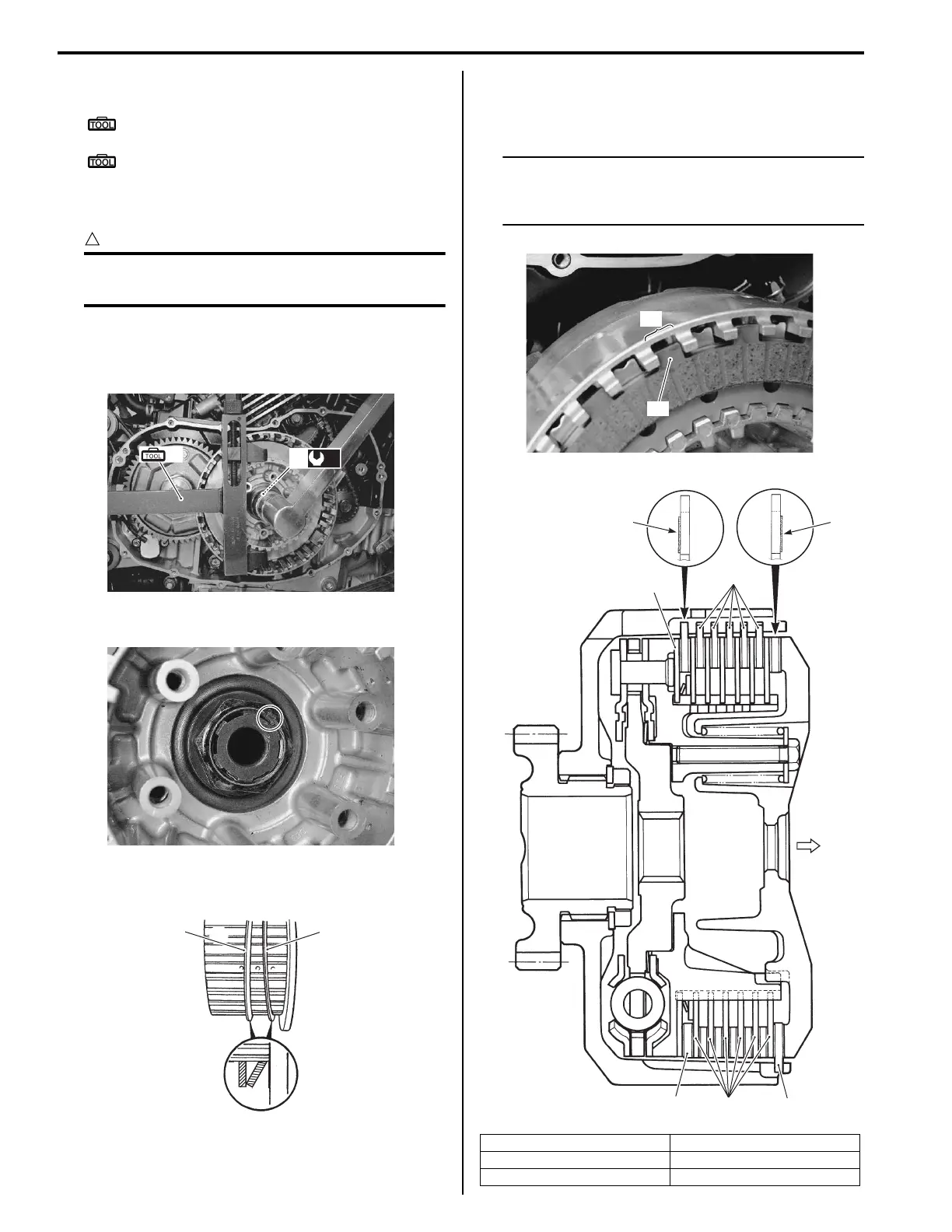
4) Hold the clutch sleeve hub with the special tools.
Special tool
(A): 09920–53740 (Clutch sleeve hub
holder)
: 09920–31020 (Extension handle)
5) Tighten the new clutch sleeve hub nut (8) to the
specified torque.
CAUTION
!
Do not use the removed clutch sleeve hub
nut.
Tightening torque
Clutch sleeve hub nut (a): 95 N·m (9.5 kgf-m,
68.5 lb-ft)
6) Lock the clutch sleeve hub nut with a center punch.
7) Install the spring washer (9) and spring washer seat
(10) onto the clutch sleeve hub correctly.
8) Insert the clutch drive plates and driven plates one
by one into the clutch sleeve hub in the prescribed
order.
NOTE
Insert the outermost No. 2 drive plate claws
“A” to the other slits “B” of clutch housing as
shown in the figure.
(A)
(a)
8
I822H1530021-02
I822H1530022-01
9
10
I822H1530024-03
11. No. 1 driven plate 14. No. 2 drive plate
12. No. 1 drive plate “C”: Direction of outside
13. No. 2 driven plate “D”: Facing side
“A”
“B”
I822H1530025-01
11
“C”
14
13
13
“D”
“D”
12
I822H1530036-06

Table of Contents

Questions and Answers:

Question and Answer IconNeed help?

Do you have a question about the Suzuki VLR1800 and is the answer not in the manual?

Suzuki VLR1800 Specifications

General IconGeneral
ManufacturerSuzuki
ModelVLR1800
Compression Ratio10.5:1
Fuel SystemFuel injection
StarterElectric
Transmission5-speed
CategoryCruiser
Displacement1783 cc
IgnitionElectronic ignition (Transistorized)
Final DriveShaft
Front SuspensionTelescopic, coil spring, oil damped
Rear SuspensionLink type, coil spring, oil damped
Rear BrakesSingle disc
Ground Clearance140 mm
Seat Height705 mm

Related product manuals