114 Part F: Configuring Channels © Tait Electronics Limited December 2007
Signal Path
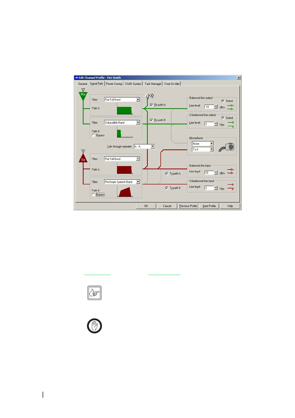
In the Add or Edit Channel Profile dialog, the Signal Path tab lets you configure
the path that incoming and outgoing signals take. In effect, you can design your
own virtual backplane for the base station.
The left-hand side of the tab defines RF filter characteristics. Each panel has a
drop-down list you can choose from, and a thumbnail graphic showing you the
response characteristics of the filter you chose.
The middle of the tab displays possible audio paths as light gray lines. Check
boxes and a drop-down list let you select path options. When you select an
item, the path it enables appears as a thick green (transmit path) or red (receive
path) line.
Both the receiver and the transmitter have two paths. Path A connects to a
balanced line
and Path B to an unbalanced line. You can select different filters
for each path.
Note: You can use Task Manager to disconnect or re-connect parts
of the signal path in particular circumstances. See “Channel Profile
Actions” on page 211. Also, Task Manager actions can connect the
balanced line input to the balanced line output, or the unbalanced line input to
the unbalanced line output. See “Loopback actions” on page 206.
Important: The transmitter can be keyed from several different
sources. If the instruction to key up is received from more than one
keying source, the source with the highest priority level takes
precedence. Only the audio that belongs to the keying source will be used to
modulate the transmission. The keying sources and their priority levels are:

 Loading...


