178 Part H: Diagnosing © Tait Electronics Limited December 2007
When you have finished testing the outputs, click Stop Test. This returns all
digital outputs to the state they were in when you started the test.
Testing the Rx Gate Output
The SK can test the Rx Gate output. You toggle the output between its two
states, active
and inactive, to make sure that the output is working or to check
that the equipment attached to the output responds as intended.
To test the Rx Gate output
1. Select Diagnose > Reciter > Digital I/O.
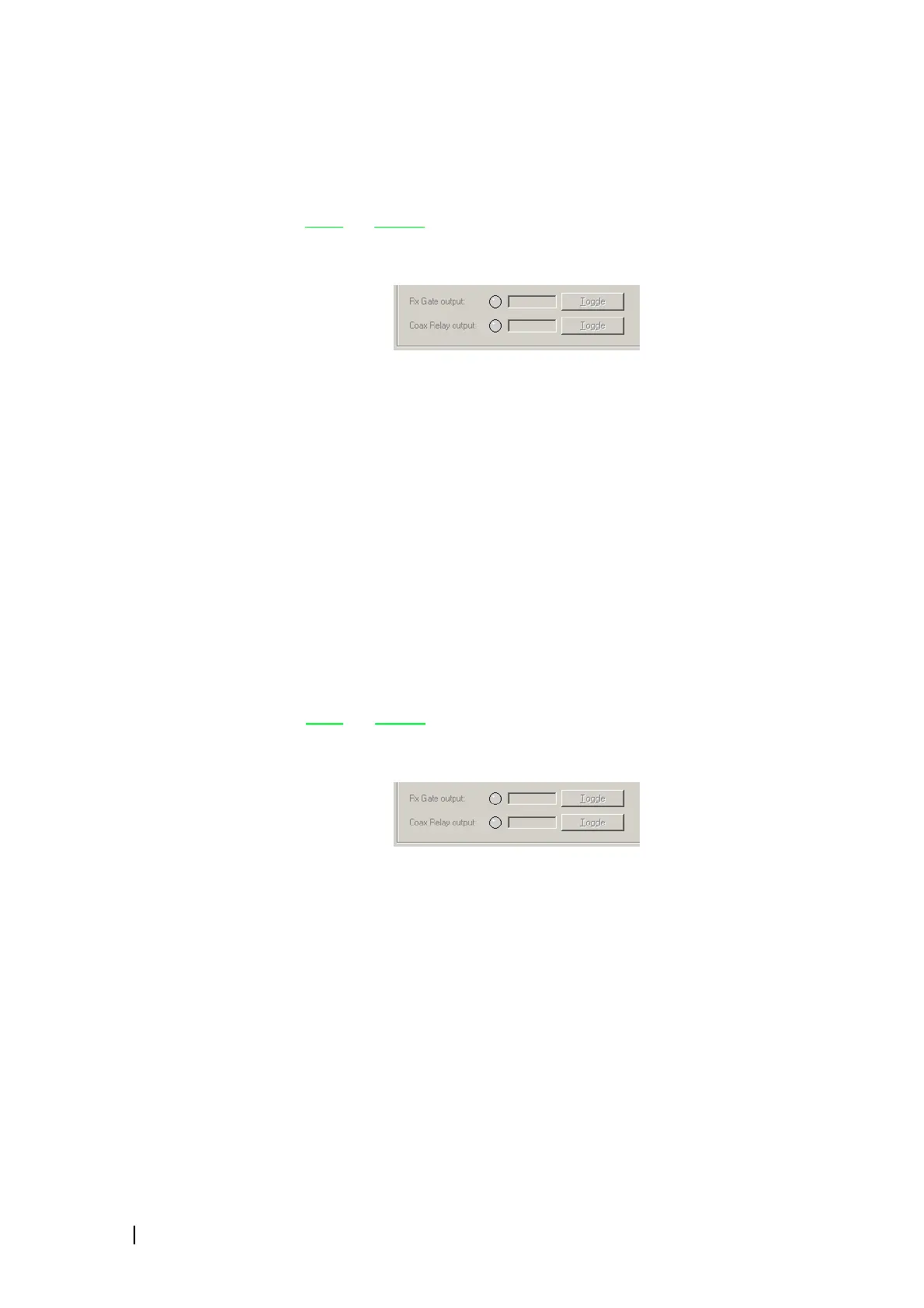
2. Click Start Test. This enables the Toggle buttons. The Rx Gate output
box now displays the state of the Rx Gate line.
3. Click the Toggle button alongside the Rx Gate output box, to change its
state.
When the Rx Gate output line is active, its LED displays green. (If the out-
put is not present on the system interface board, an error message appears.)
4. Check the response of any attached equipment. A green LED means
‘unmuted.’
5. When you have finished testing the output, click Stop Test. This returns
the Rx Gate output to the state it was in when you started the test.
Testing the Coaxial Relay Driver
The SK can test the coaxial relay driver. You toggle its output between its two
states, active
and inactive, to make sure that the driver is working or to check
that the relay responds as intended.
To test the coaxial relay driver output
1. Select Diagnose > Reciter > Digital I/O.
2. Click Start Test. This enables the Toggle buttons. The Coax Relay output
box now displays the state of the coaxial relay driver.
3. Click the Toggle button alongside the Coax Relay output box, to change
the state of the coax relay driver output.
When the Coax Relay output line is active (in Transmit mode), its LED dis-
plays green. (If the output is not present on the system interface board, the
display is disabled. If the TaitNet Ethernet system interface board is fitted,
an internal link must select the Coax relay driver output.)
4. Check the response of any attached equipment.
5. When you have finished testing the output, click Stop Test. This returns
the coaxial relay driver output to the state it was in when you started the test.

 Loading...


