176 Part H: Diagnosing © Tait Electronics Limited December 2007
4. In the Input area, click Start Test.
The Audio Input gauge displays the audio level. The numeric value of the
level appears under the gauge heading. The value is displayed in red if it is
off the scale of the gauge. Levels are measured over a window of 100 ms and
updated twice a second.
5. Click Stop Test or return to Run mode to end the test.
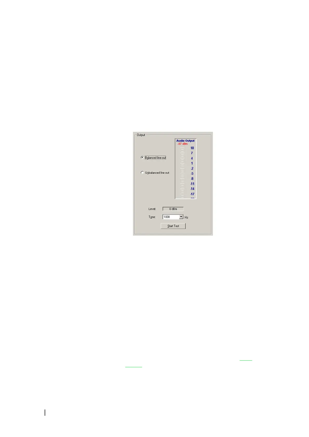
Generating an Audio Output
The reciter can output an audio test tone at one of three pre-defined
frequencies. You can use this to test the reciter's ability to put audio on its
output lines or to set up and configure the interface from external equipment
to the base station. The audio is output at a nominal 0 dBm.
1. Select Diagnose > Reciter > Audio I/O.
2. In the Output area, specify which line out will carry the output.
3. Click Start Test.
4. View the Audio Output gauge and check that the measured level is close
to 0 dBm (balanced line out) or 0.8 Vpp (unbalanced line out).
5. Click Stop Test or return the base station to Run mode to end the test.
Digital I/O Tests
The Digital I/O form (Diagnose > Reciter > Digital I/O) lets you work with
digital inputs and outputs. You can view the current state of all digital inputs
and toggle any digital output to help you test any equipment connected to it.
The Hardware channel number box indicates the channel number that is
currently set by external equipment using the channel select lines on the system
interface. If the box is disabled, this is because external channel selection is
disabled (Configure > Base Station > System Interface.)
The Digital outputs area lets you toggle any digital output between active
(green LED) and inactive
(gray LED). You can do the same to the Rx Gate and
Coax Relay outputs.

 Loading...


