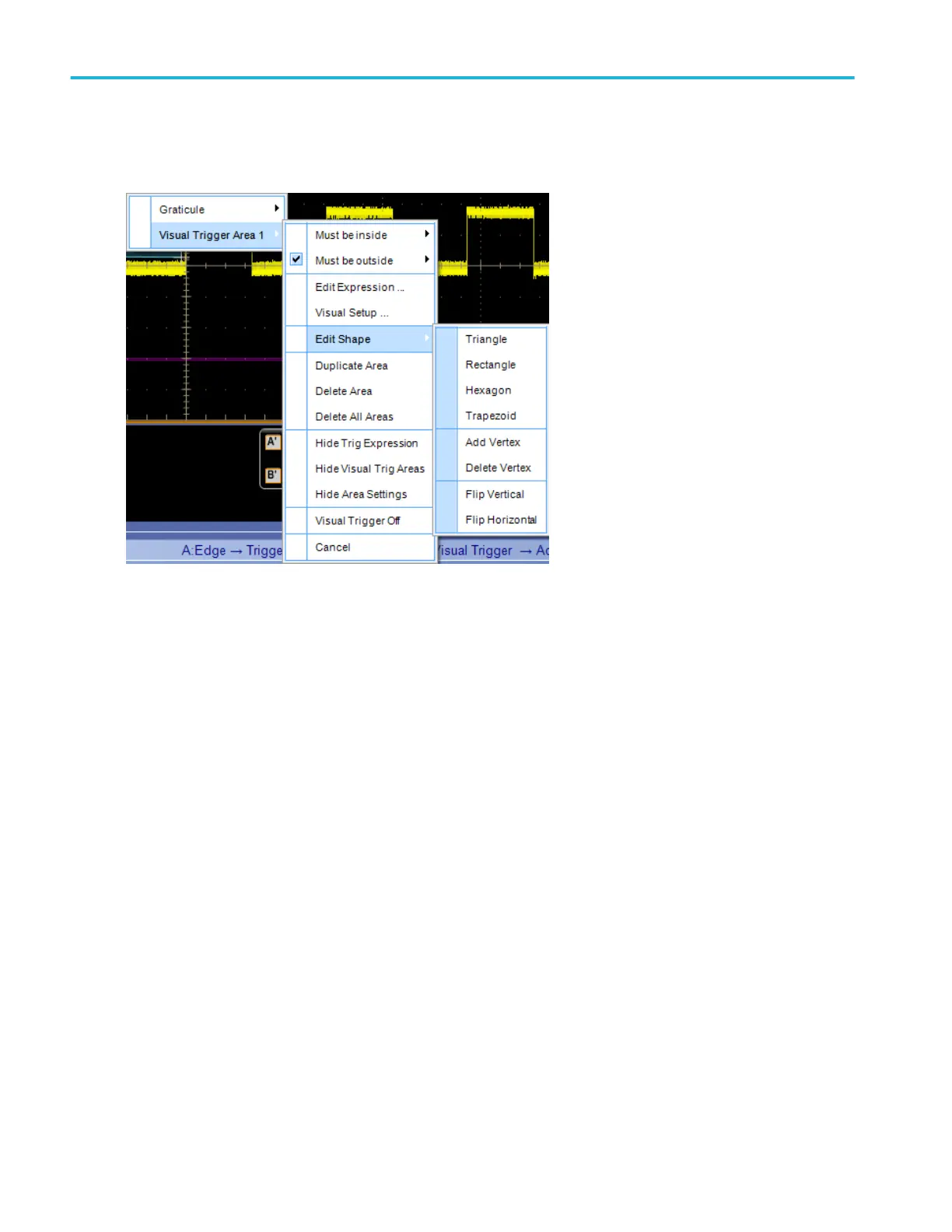
To use. Right click a visual trigger area and select Visual Trigger Area.
Select Edit Shape to change the shape and orientation of the visual trigger area. Selections include the following:
■
Triangle
■
Rectangle
■
Hexagon
■
Trapezoid
■
Add Vertex. After adding a vertex, if vertices are not enabled, double click the visual trigger area. Then select each vertex
and drag it to its desired location.
■
Delete Vertex
■
Flip Vertical
■
Flip Horizontal
■
Select Must be inside, Must be outside, or Edit Equation to create the qualification expression:
■
Must be inside specifies which channel the area must be inside.
■
Must be outside specifies which channel the area must be outside.
■
Edit Equation opens the Qualification Expression Editor, allowing you complete control over the qualification expression.
Select what is displayed:
■
Hide Trig Expression toggles display of the trigger expression on and off.
■
Hide Visual Trig Areas toggles display of all visual trigger areas on and off.
■
Hide Area Settings toggles display of the area settings on and off.
■
Visual Trigger Off toggles visual triggering on and off.
What do you want to do next?
Trigger setups
466 DPO70000SX, MSO/DPO70000DX, MSO/DPO70000C, DPO7000C, and MSO/DPO5000B Series
 Loading...

