Compensate passive probes
Use this procedure to optimize gain and offset accuracy at the probe tip. Allow the instrument to warm up before performing this
procedure.
Perform the low frequency probe compensation for passive probes.
NOTE. The probe compensation procedure is not recommended for the P5050 passive probes. These probes have little gain or
offset errors. However, you should perform this procedure for other passive probes.
Complete the following steps:
1. If you have not already done so, connect the probe to the instrument.
2. Connect the probe to probe compensation (Fast Edge on some models) terminals as shown. Connect only one probe at a
time.
3. Select Probe Cal from the Vertical menu to open the Probe Compensation control window.
4. Select the channel to which the probe is attached.
5. Click Compensate Probe to begin the procedure. The Probe Status indicator changes to Pass when the procedure is
complete. If the procedure does not pass, contact your local Tektronix service personnel.
6. Remove the connections from the terminals.
Low frequency compensate a probe
Use this procedure to compensate passive probes to ensure maximum distortion-free inputs to the instrument.
1. Connect the probe to Ch 1 on the instrument.
2. Attach the probe tip and reference lead to the probe compensation terminals .
3. Press the Autoset button on the instrument.
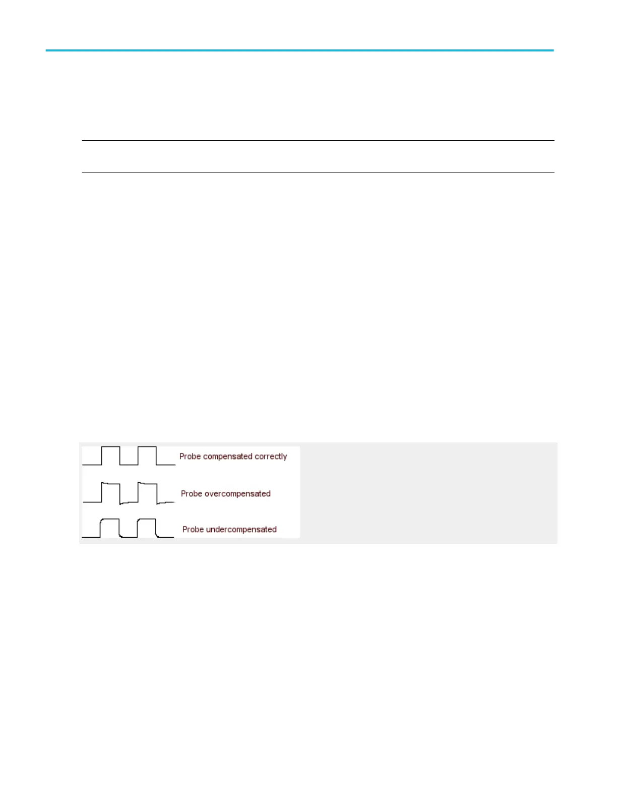
4. Adjust the probe until you see a square wave with a perfectly flat top on the display.
5. See your probe manual for adjustment instructions.
Deskew
Use the following procedure to compensate for timing differences between voltage probes:
1. Set up the instrument to display all of the channels that you want to deskew.
2. Push the instrument Autoset button.
3. Adjust the vertical Scale and Position controls for each channel so that the signals overlap and are centered on the display.
4. Adjust the horizontal Position so that a rising edge is triggered at the center of the display.
5. Adjust the horizontal Scale so that the differences in the channel delays are clearly visible.
6. Adjust the horizontal Position again so that the first rising edge is exactly at the center of the display. The fastest probe is
connected to this channel (the fastest probe is usually the one with the shortest cable or with the highest bandwidth).
7. Select Deskew from the Vertical menu to open the Deskew control window.
How to ?
576 DPO70000SX, MSO/DPO70000DX, MSO/DPO70000C, DPO7000C, and MSO/DPO5000B Series
 Loading...

