Setup/hold triggering uses the setup/hold violation zone to detect when data is unstable too near the time it is clocked. Each time
trigger holdoff ends, the instrument monitors the data and clock sources. When a clock edge occurs, the instrument checks the
data stream it is processing (from the data source) for transitions occurring within the setup/hold violation zone. If any occur, the
instrument triggers with the trigger point located at the clock edge.
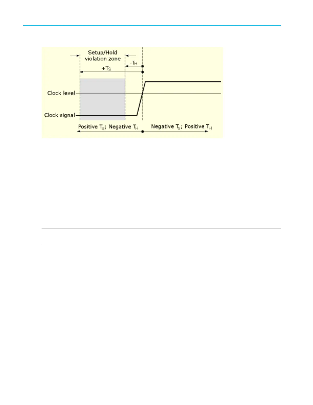
Positive settings for both setup and hold times (the most common application) locate the setup/hold violation zone so that it
spans the clocking edge as shown above in the top waveform. The instrument detects and triggers on data that does not become
stable long enough before the clock (setup time violation) or that does not stay stable long enough after the clock (hold time
violation).
Negative settings for setup or hold times skew the setup/hold violation zone to locate it before or after the clocking edge as
shown above in the center and bottom waveforms. The instrument can then detect and trigger on violations of a time range that
occurs before or one that occurs after the clock.
NOTE. Keep the hold-time setting to no more than 2.5 ns less than one-half the clock period (hold time < (period/2) –2.5 ns) or
the instrument cannot trigger (this assumes a 50% duty cycle clock).
State trigger
A state trigger occurs when the inputs to the logic function cause the function to become True or False at the time the clock input
changes state. When you use a state trigger, you define:
■
The precondition for logic input channels 1 through 3
■
The direction of the state change for the clock input, channel 4
■
The Boolean logic function: AND, NAND, OR, or NOR
■
The condition for triggering: the Boolean function becomes True (logic high) or False (logic low)
State trigger logic conditions are summarized in the following table.
Oscilloscope reference
672 DPO70000SX, MSO/DPO70000DX, MSO/DPO70000C, DPO7000C, and MSO/DPO5000B Series
 Loading...

