Pattern State Definition
7
,
8
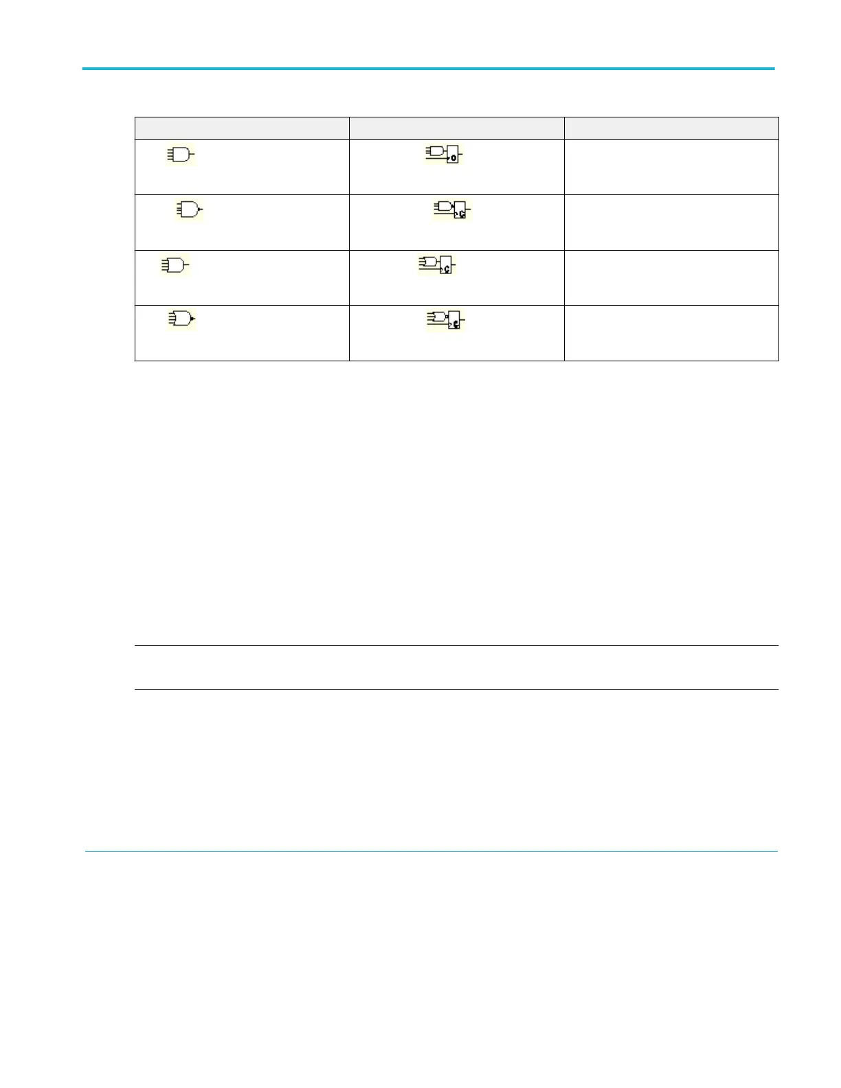
AND
Clocked AND
If all the preconditions selected for the
logic inputs
9
are TRUE, then the
instrument triggers.
NAND Clocked NAND
If not all of the preconditions selected for
the logic inputs
10
are TRUE, then the
instrument triggers.
OR
Clocked OR
If any of the preconditions selected for the
logic inputs
11
are TRUE, then the
instrument triggers.
NOR
Clocked NOR
If none of the preconditions selected for
the logic inputs
12
are TRUE, then the
instrument triggers.
Timeout trigger
A timeout trigger occurs when the instrument does not detect an expected pulse transition within a user specified period of time,
such as when a signal gets stuck either high or low. If the pulse transition occurs prior to a specified timeout time (the expected
case), then no trigger results.
Transition time trigger
Transition triggering is based on the slope (change in voltage/change in time) of a pulse edge.
Use the transition trigger to trigger the instrument on pulse edges that traverse between two thresholds at faster or slower rates
than the specified time. You can set up the instrument to trigger on positive or negative edges.
Video trigger
Use the Video trigger to trigger the instrument on specified fields or lines of a composite video signal. You can select from
several preset video signal formats or set a custom format.
NOTE. Only composite signal formats are supported. Graphic display formats such as RGB and VGA are not supported. Video
trigger is not available on some instruments.
7
For state triggers, the definition must be met at the time the clock input changes state.
8
The definitions given here are correct for the Goes TRUE setting in the Trigger When menu. If that menu is set to Goes False, swap the definition for AND with that for
NAND and for OR with NOR for both pattern and state types.
9
The logic inputs are channels 1, 2, 3, and 4 when using Pattern triggers. For State triggers, channel 4 becomes the clock input, leaving the remaining channels as logic
inputs.
10
The logic inputs are channels 1, 2, 3, and 4 when using Pattern triggers. For State triggers, channel 4 becomes the clock input, leaving the remaining channels as logic
inputs.
11
The logic inputs are channels 1, 2, 3, and 4 when using Pattern triggers. For State triggers, channel 4 becomes the clock input, leaving the remaining channels as logic
inputs.
12
The logic inputs are channels 1, 2, 3, and 4 when using Pattern triggers. For State triggers, channel 4 becomes the clock input, leaving the remaining channels as logic
inputs.
Oscilloscope reference
DPO70000SX, MSO/DPO70000DX, MSO/DPO70000C, DPO7000C, and MSO/DPO5000B Series 673
 Loading...

