Refrigeration Maintenance and Service Operations
147
3. Solder liquid line inlet and outlet line
connections to valve.
NOTE: Thermo King strongly recommended
that dry nitrogen be used to purge the system
during any solder operations (see “Using
Pressurized Nitrogen” in this chapter).
4. Solder equalizer line to expansion valve.
5. Pressurize the refrigeration system and check
for leaks (see “Refrigerant Leak Test
Procedure” in this chapter).
6. If no leaks are found, recover the refrigerant
used for the leak test (see “Refrigerant
Recovery” in this chapter).
7. Evacuate the system (see “Evacuation and
Cleanup of the Refrigeration System” in this
chapter).
8. Clean the suction line to a bright polished
condition. Install the feeler bulb of new power
head in the feeler bulb clamp on the suction
line. Locate bulb on the suction line in former
position. The feeler bulb must make good
contact with the suction line or operation will
be faulty. Cover with insulating tape.
9. Cover expansion valve outlet line with
insulating tape.
10. Recharge the unit with R-404A (see
“Charging the System with Refrigerant” in
this chapter).
11. Perform a controller pre-trip test to verify
system operation and correct feeler bulb
installation.
Heat Exchanger Replacement
Removal
1. Recover the refrigerant charge from the unit
(see “Refrigerant Recovery” in this chapter).
2. Remove the “U” mounting clamps that hold
the heat exchanger assembly to the wall of the
condenser section.
3. Unsolder the liquid inlet and outlet line
connections.
4. Note position of feeler bulb on the side of the
suction line. Remove tape and feeler bulb
from the suction line.
5. Unsolder the suction inlet and outlet line
connections.
6. Lift the heat exchanger assembly from the
unit.
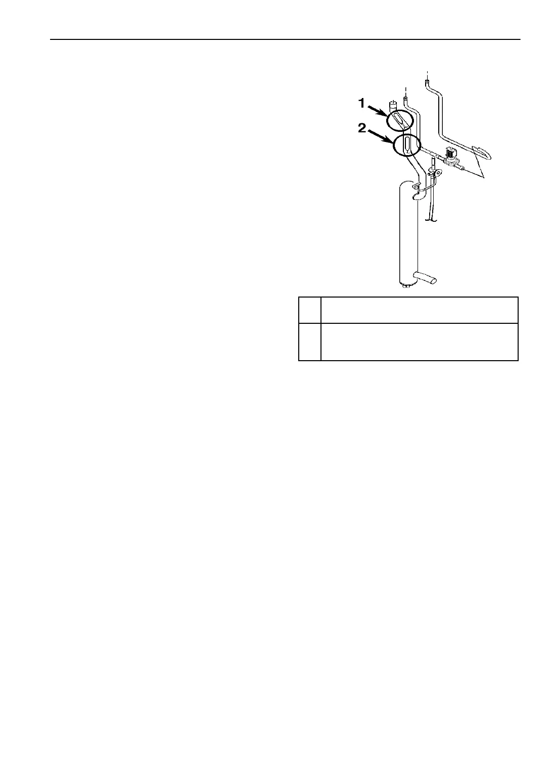
1.
Normal Feeler Bulb Location in Evaporator
Section
2.
Temporary Feeler Bulb Location in Condenser
Section when Replacing the Expansion Valve
on a Loaded Container
Figure 53: Expansion Valve Feeler Bulb Location
AXA0247

 Loading...