Home
Thermo King
Refrigerator
CSR Series
Thermo King CSR Series User Manual
5
of 1
of 1 rating
189 pages
Give review
Manual
Specs
To Next Page
To Next Page
To Previous Page
To Previous Page
Loading...
Unit
Descri
ption
43
AXA0233
1
2
3
4
5
6
10
9
8
7
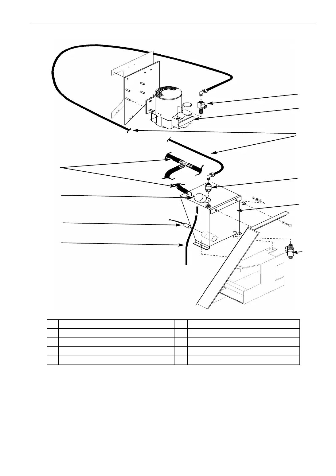
1.
Evaporat
or Drain
Hose
6.
W
ater T
ank
2.
Fill Ca
p
7.
Water Filter
3.
W
ater T
ank Heat
er
8.
W
ater Supply
Hose
4.
T
ank O
verfl
ow Ho
se
9.
Air
Compre
ssor
5.
Drain
Cock
10.
Liquid
Spray N
ozzle
Figure 1
3:
Humidi
fy Syste
m Option
42
44
Table of Contents
Default Chapter
5
Table of Contents
5
List of Figures
11
Safety Precautions
13
General Practices
13
Refrigerant
13
First Aid
13
Refrigerant Oil
13
Electrical
14
High Voltage
14
Servicing Units (or Containers) Equipped with a Microprocessor Controller
15
Controller Repair
15
Welding of Units or Containers
15
Unit Decals
16
Serial Number Locations
16
Figure 1:Nameplate and Warning Locations
16
Service Guide
17
Specifications
19
System Net Cooling Capacity- Full Cool
19
Evaporator Airflow
20
Electrical System
21
Refrigeration System
22
Normal R-404A System Operating Pressures (Scroll Compressor)
23
MP-3000 Controller
24
Dehumidify and Humidify Systems (Options)
25
Physical Specifications
26
Figure 2:Physical Specifications
27
Metric Hardware Torque Charts
28
Unit Description
29
General Description
29
Scroll Compressor with Liquid Injection Cooling System
29
MP-3000 Controller
29
Dual Speed Evaporator Fans
30
Fresh Air Exchange System
30
Unit Options
30
Advanced Fresh Air Management (AFAM)
30
Advanced Fresh Air Management Plus (AFAM+)
30
Bulb Mode
30
Dehumidification Control System
30
Dual Voltage
31
Humidification Control System
31
Pressure Gauge Options
31
Remote Monitoring Modem (RMM)
31
Remote Monitoring Receptacle (4-Pin)
31
Recording Thermometer Options
31
TRANSFRESH Atmosphere Control System Options
31
USDA Cold Treatment Temperature Recording
31
Water-Cooled Condenser/Receiver Tank
32
Operating Modes
32
Chill Loads: Controller Setpoint at -9.9 C (14.1 F) or above
32
Frozen Loads: Controller Setpoint at -10 C (14 F) or below
32
Figure 3:Typical Unit Front View
33
Figure 4:Evaporator Front View - CSR20SL & CSR40SL
34
Figure 5:Evaporator Front View - CSR40
35
Figure 6:Options - Unit Front View
36
Figure 7:CSR20SL, CSR20SL, CSR40SL & CSR40SL Options - Evaporator Front View
37
Figure 8:CSR40 & CSR40 Options - Evaporator Front View
38
Figure 9:Refrigeration System
39
Figure 10:Scroll Compressor
40
Figure 11:MP-3000 Controller
41
Figure 12:Unit Control Box
42
Figure 13:Humidify System Option
43
Figure 14:Advanced Fresh Air Management (AFAM) Option
44
Figure 15:Advanced Fresh Air Management (AFAM+) Option
45
Figure 16:TRANSFRESH Provision Option
46
Figure 17:TRANSFRESH System, Complete
47
Figure 18:Unit Back View - All Models Without Heater Access Door
48
Figure 19:Unit Back View - Models with Heater Access Door (CSR20SL-144 , CSR40-145, CSR20SL-155 and CSR40SL-506)
49
Operating Instructions
51
Unit Controls
51
Unit Control Box
51
MP-3000 Controller
51
Other Unit Controls
52
Unit Instruments
52
Unit Protection Devices
53
Figure 20:Control Circuit Fuses
53
Table of Cont Ents
55
MP-3000 Controller
55
Controller Description
55
Figure 21:Controller
55
Status Indicator Leds
58
Data Recording and Downloading Data
59
General Theory of Operation
59
Chill Loads: (Setpoint at -9.9 C [14.1 F] and Above)
60
Frozen Loads: (Setpoint at -10 C [14 F] and Below)
61
Compressor Liquid Injection
61
Warm Gas Bypass
61
Power Limit Mode
62
Evaporator Fan Control
62
Condenser Fan Control
62
Probe Test
62
Bulb Mode (Option)
63
Dehumidify Mode (Option)
63
Sequence of Operation
63
Unit Start-Up
63
Continuous Temperature Control Operation
64
Figure 22:Chill Load Control Sequence (Setpoints at -9.9 C [14.1 F] and Above)
64
Frozen Loads (Controller Setpoint at -10 C [14 F] and Below)
66
Figure 23:Frozen Load Control Sequence (Setpoints at -10 C [14 F] and Below)
67
Changing the Setpoint
68
Initiating a Manual Defrost
69
Displaying Alternate Controlling (Supply or Return) Air Sensor Temperature
69
Displaying Alternate Fahrenheit (F) or Celsius (C) Temperatures
69
Navigating the Controller Menu
69
General Operating Tips
70
Setpoint Menu
70
Changing the Setpoint Temperature
70
Changing the Bulb Mode Setting
70
Changing the USDA Trip Setting
71
Figure 24:Setpoint Menu Screen Flow Diagram
72
Changing the Economy Mode Setting
73
Changing the Humidity Mode Setting
73
Changing the Humidity Setpoint
73
Setting
73
Changing the AFAM Delay
74
Changing the AFAM Rate
75
Changing the O Minimum Setting
75
Changing the CO Maximum Setting
76
Data Menu
76
Viewing the Data Menu
76
Alarms Menu
77
Alarm Types
77
Alarm Code States
77
Figure 25:Data Menu Screen Flow Diagram
77
Viewing the Alarm List Menu
78
Alarm List
78
Figure 26:Alarms Menu Screen Flow Diagram
78
Commands Menu
79
Viewing the Commands Menu
79
Function Test
81
Figure 27:Commands Menu Screen Flow Diagram
81
Pre-Trip (PTI) Test
84
Manual Function Test
88
Power Management
89
Misc. Functions Menu
90
Viewing the Misc. Functions Menu
90
Setting the Date and Time
91
Figure 28:Misc. Functions Menu Screen Flow Diagram
91
Viewing or Setting Run Time
92
Setting Cargo Data
92
Changing the Temperature Display Value (C/F)
93
Configuration Menu
93
Viewing or Setting Functions
93
MP-3000 Controller (Continued)
94
Datalogger Menu
95
Figure 29:Configuration Menu Screen Flow Diagram
95
Inspect Temp Log
96
Viewing the Datalogger Menu
96
Calibrate USDA Probe
97
Figure 30:Datalogger Menu Screen Flow Diagram
97
Inspect Event Log
97
Set a Trip Start
98
Inspect Event Log
99
Set a Trip Start
99
Set Log Time
99
RMM State Menu
100
Viewing the RMM State Screen
100
Manual Emergency Mode Operation
100
Figure 31:RMM Menu Screen Flow Diagram
100
Figure 32:Manual Emergency Control Connections
101
Reversing Power Phase on CSR Units
102
Replacing the Controller
102
Automatic Configuration of Spare Parts Controller
103
Controller Software Selection
103
Flash Loading Controller Software
103
Temperature Sensors
104
Figure 33:CSR20SL and CSR40SL Evaporator Coil (Defrost) Sensor Location
104
Figure 34:CSR40 Evaporator Coil (Defrost) Sensor Location
104
Figure 35:Condenser Coil Sensor Location
105
Diagnosis and Repair
106
External Cause Checks
106
Error Messages and Controller Actions
107
Alarm Codes, Descriptions and Corrective Actions
109
Electrical Maintenance
127
High Pressure Cutout Switch
127
High Pressure Cutout Manifold
127
Figure 36:High Pressure Cutout Manifold
127
Low Pressure Cutout Switch
128
Condenser Fan and Evaporator Fan Rotation
128
Condenser Fan
128
Evaporator Fans
128
Electric Heaters
129
Refrigeration Maintenance and Service Operations
131
Service Tools
131
Unit Service Fittings
131
Leak Detection
131
Gauge Manifold Set
131
Figure 37:Service Fittings Specifications
131
Vacuum Pump
132
System Cleanup
132
Refrigerant Recovery
132
Compressor Oil Acid Test
132
Compressor Discharge and Suction Service Valves
132
Figure 38:Service Valve Back Seated
132
Figure 39:Service Valve Open to Port
132
Figure 40:Service Valve Front Seated
132
Gauge Manifold Valve Positions
133
Figure 41:Balancing the Pressure
133
Figure 42:Removing Refrigerant
133
Figure 43:Gauge Manifold Closed to Center Port
133
Figure 44:Gauge Manifold Open to Center Port
133
Figure 45:Charging the System
133
Gauge Manifold Set (with Low Loss Fittings) Attachment and Purging
134
Gauge Manifold Set Installation
134
Figure 46:Purging Gauge Manifold
134
Gauge Manifold Set Removal
135
Checking Compressor Oil
135
To Check Compressor Oil Level with an Ambient Air Temperature above 10 C (50 F)
135
To Check Compressor Oil Level with an Ambient Air Temperature below 10 C (50 F)
135
Figure 47:Adjusting Compressor Oil Level
135
Adding Compressor Oil
136
Removing Excess Compressor Oil
136
Refrigerant Charge
136
Refrigerant Leak Test Procedure
136
Using Pressurized Nitrogen
137
Safety Precautions
137
Figure 48:Test for Refrigerant Leaks
137
Procedure
138
Refrigerant Recovery
138
Vapor Recovery
138
Figure 49:Typical Pressurized Gas Bottle with Pressure Regulator and Gauges
138
Table of Cont Ents
139
Refrigeration Maintenance and Service Operations (Continued)
139
Evacuation and Cleanup of the Refrigeration System
139
Compressor Oil Color Code
139
Unit Preparation and Hookup
139
Unit Evacuation
140
Figure 50:Evacuation Station and Unit Hook-Up
141
Pressure Rise Test
142
Figure 51:Constant Pressure Rise after Evacuation Indicates System Leak
142
Figure 52:Pressure Rise Levels off after Evacuation Indicates Moisture in System
142
Factors Affecting the Speed of System Evacuation
143
Heat Saves Time
143
List of Figures
141
Charging the System with Refrigerant
143
Unit Charging by Weight (from an Evacuated Condition)
143
Evacuation Station Removal
143
Compressor Replacement
144
Removal
144
Installation
145
Stepper Motor Valve Replacement
144
Replacement
144
Condenser Coil Replacement
145
Removal
145
Expansion Valve Replacement
146
Filter Drier/In-Line Filter Replacement
146
Removal
146
Installation
146
Heat Exchanger Replacement
147
Removal
147
Figure 53:Expansion Valve Feeler Bulb Location
147
Installation
148
Low or High Pressure Cutout Switch Replacement
148
Installation
149
Receiver Tank Replacement
148
Removal
148
Compressor Discharge Temperature Sensor or High Pressure Cutout Switch
149
Removal
149
Warm Gas Bypass Valve, Liquid Injection Valve or Coil/Dehumidify Valve Replacement
149
Structural/Accessory Maintenance
151
Mounting Bolts
151
Unit Inspection
151
Condenser Coil
151
Evaporator Coil
151
Defrost Drains
151
Figure 54:Mounting Bolts
151
Condenser Fan Location
152
Evaporator Fan Location
152
Fresh Air Exchange System
152
Disk Adjustment: Low Ventilation Rates
152
Figure 55:Condenser Fan Blade Placement
152
Figure 56:Evaporator Fan Blade Placement
152
Handle Adjustment: High Ventilation Rates
153
(Options)
153
Figure 57:Air Exchange System
153
Humidify System (Option)
154
Figure 58:AFAM System Linkage Adjustment
154
Figure 59:Humidify System (Option)
154
Inspection and Cleaning
155
Pre-Trip Inspection
155
Partlow (Model SR) Recording Thermometer (Option)
155
Recording Chart Replacement
155
Marking System Calibration
156
Figure 60:Partlow (SR) Recording Thermometer
156
Element Replacement
157
Saginomiya (Model SKM) Recording Thermometer (Option)
157
Figure 61:Saginomiya (SKM) Recording Thermometer
157
Battery
158
Marking System Calibration
158
Recording Chart Replacement
158
Power Element Assembly Replacement
159
Timer (Quartz Motor and Reducing Gear) Replacement
159
Battery Voltage Indicator
160
Diagnosis
161
Mechanical Diagnosis
161
Refrigeration Diagnosis
163
AFAM System & AFAM
167
Advanced Fresh Air Management (AFAM) System
167
Setting AFAM System Values
167
Figure 62:AFAM System
167
Changing the AFAM Delay
168
Starting the AFAM System
168
Changing the AFAM Rate
169
Figure 63:Setpoint Menu Screen Flow Diagram
169
Figure 64:Configuration Menu Screen Flow Diagram
170
Setting AFAM Units in the Configuration Menu
170
Advanced Fresh Air Management Plus (AFAM+) System
171
Setting AFAM+ System Values
171
Starting the AFAM+ System
171
Figure 65:AFAM+ System
171
Changing the AFAM Delay
172
Changing the O Minimum Setting
172
Changing the CO Maximum Setting
173
Index
175
Wiring and Schematic Diagrams Index
177
5D55643 CSR Wiring Schematic
179
5D55644 CSR Wiring Diagram
180
5D52861 MPC 2000ID/MP3000 Controller High Voltage Wiring Diagram
182
5D52862 MPC 2000ID/MP3000 Controller Low Voltage Wiring Diagram
183
CSR Wiring Schematic MPC 2000ID/MP3000 Receiver 2 Fan Schematic Diagram
184
CSR Refrigeration System Components
185
Flow and Pressure Diagram, CSR
187
Flow and Pressure Diagram, CSR, Dehumidification
188
MP-3000 Menu Flow Diagram
189
5
Based on 1 rating
Ask a question
Give review
Questions and Answers:
Need help?
Do you have a question about the Thermo King CSR Series and is the answer not in the manual?
Ask a question
Thermo King CSR Series Specifications
General
Brand
Thermo King
Model
CSR Series
Category
Refrigerator
Language
English
Related product manuals
CSR40-145 Power Saver
189 pages
CSR20SL-144 Power Saver
189 pages
Thermo King CSR-40SL-126
199 pages
Thermo King CSR-20 Series
199 pages
Thermo King V250
127 pages
Thermo King MD-MT
192 pages
Thermo King UT-800
169 pages
Thermo King T-600R
68 pages
Thermo King T-800R
68 pages
Thermo King SLXi-100
68 pages
Thermo King SLXi-300
342 pages
RD-II SR 50 380-460/3/50-6
136 pages

 Loading...