Structural/Accessory Maintenance
155
The evaporator drain hoses are routed to the water
tank to replenish the water level during unit
operation. However, water usage will vary
depending upon the load and ambient conditions.
An overflow hose on the water tank removes
excess water when particularly wet loads are
transported or when the humidify system is not
operating.
NOTE: Only demineralized or distilled water
should be used to prevent plugging of the
atomizing nozzle.
Pre-trip Inspection
The following items should be inspected before
loading the container:
• Check the water level in the water tank to
maintain an
• adequate water supply.
• Check humidify system operation by starting
the unit, setting the Humidify mode to On and
adjusting the humidify setpoint (HUMSP)
more than 2% above the current humidity
level in the container. Verify that the air
compressor operates and that water is drawn
into the atomizing nozzle and injected into the
return air stream.
Inspection and Cleaning
The following items should be periodically
serviced:
• Clean and inspect the filter in the water supply
hose on the water tank every 1,000 operating
hours. Clean the filter screen with fresh water
and a soft brush.
• Inspect the water tank, water supply line and
atomizing nozzle every 1,000 hours and clean
if necessary. Use fresh water, a soft brush and
compressed air to clean and blow clear
components.
• Inspect the air compressor for signs of
overheating once a year.
Partlow (Model SR) Recording
Thermometer (Option)
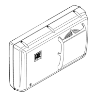
The 31-day Partlow Recorder is mechanically
driven by a spring wound mechanism. The sensor
bulb is mounted in the evaporator to record the
supply air temperature.
The recording thermometer should be inspected
and cleaned to ensure that the stylus produces
smooth clean lines and records accurate
temperature readings. When changing charts,
wipe the stylus and chart platen with a clean,
damp cloth to remove material transferred from
the back of the chart to the platen by the pressure
of the stylus.
Recording Chart Replacement
1. To change the charts, remove the knurled
chart nut from the drive shaft and remove the
chart.
2. Install the new chart on the chart drive shaft.
Position the chart edge under the four clips.
3. Replace the chant nut loosely and rotate the
chart so that the correct time is indicated by
the stylus. In order to operate the stylus with
the door open for the purpose of checking or
zeroing the control, the lifter arm can be
locked in this lowered position by pushing
down on the lifter arm shaft and rotating the
arm on its pivot point. If the lifter arm does
not retract away from the stylus when the door
is closed, reposition the arm on the shaft by
loosening the Allen screw on the lifter arm.
4. Hold the recording chart in position and
tighten the chart nut finger tight.
5. Lower the pen by rotating the lifting arm
counterclockwise and pushing the pen against
the chart. If there is insufficient pressure on
the stylus to mark the chart, carefully grip the
pivot end of the stylus warm where it is
riveted to the stamping with a pair of
long-nosed pliers. Bend the stamping toward
the instrument. Care must be used not to bend
the stylus arm, but only the stamping to which
it is attached.
 Loading...


